
Manual

9
CF1000 Burner Manual
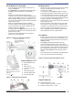
Install Nozzle Line Assembly
Insert the nozzle line assembly into the burner air
tube as in Figure 6.
See Figures 6 and 7. Assemble the adjusting plate
assembly per the instructions in the assembly
packet.
Slide the secondary adjusting plate (item f)
completely to the left on the indicator adjusting plate
(item e). Finger tighten acorn nut c to secure the two
plates together. Slide both plates completely to the
left on the primary adjusting plate (item g) and fi nger
-tighten acorn nut d.
Slide the completed adjusting plate assembly
over the nozzle line end. Move the plate assembly
and the nozzle line so the plate assembly fi ts into
position as shown in Figure 6.
Install the spline nut (Figure 6, item b) on the end of
the nozzle line, leaving the nut loosely placed so the
plates can be moved.
Connect the high-voltage leads from the ignition
transformer to the electrodes.
○
○
○
○
○
○
Set Dimension Z
Replace the rear access door on the burner, making
sure that the adjusting plate assembly is now
securely held in place.
Loosen acorn nut d in Figure 6. Slide the nozzle
line and plate assembly until dimension Z (from end
of air tube to fl at area of front face of head) is 1-3/4”
± 1/16”. When dimension Z is correctly set, tighten
acorn nut d. Verify that the adjusting plate assembly
is properly seated in the adjusting groove.
Attach the oil line from the oil valve to the nozzle line
end. Tighten securely.
Before proceeding, check dimension Z once again.
Loosen acorn nut d if necessary to reposition the
nozzle line. Once dimension Z is set, do not loosen
acorn nut d again. For the setting of acorn nut c,
refer to Adjusting Plate Assembly procedure under
‘Start the Burner’ Section of this manual.
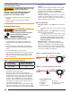
Insert Burner
Position the burner in the front of the appliance and
loosely tighten the nuts on the mounting studs. The
burner should be pitched downward 2° as shown in
Figures 3 and 4.
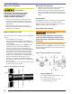
See Figure 8. Install the pedestal support kit
(recommended) by attaching the ¾” NPT fl ange
(item a) to the bottom of the burner using the (4) #10
screws provided. Cut and thread (one end only) a ¾”
pipe nipple (item b) with length 10 inches less than
dimension D in Figure 8. Thread the pipe into the
fl ange.
Secure the burner to the appliance by tightening the
nuts on the burner fl ange mounting studs.
○
○
○
○
○
○
○
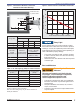
Section: Mount the Burner
Measure dimension Z
from front (fl at) face of
head to end of air tube,
as shown.
Measure dimension Z from the
fl at surface between (not on) the
raised fi ns.
Z = 1-3/4” + 1/16”
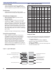
Legend (Figures 6 & 7)
a
Adjusting plate assembly
b
Spline nut
c
Bottom acorn nut
d
Top acorn nut (for setting
dim. Z only
e
Indicator adjusting plate
f
Secondary adjusting plate
g
Primary adjusting plate
Legend (Figure 8)
H Housing total length — 18”
J Center to bottom of housing — 10-7/8”
K Overall housing height — 13-3/8”
Figure 8 - Burner Installed in Appliance Front
Figure 6 - Nozzle Line Assembly in Burner
Figure 7 - Adjusting Plate Assembly