AM-510 Commercial / Residential Multimeter AM-510-EUR Digital Multimeter Users Manual
AM-510 AM-510-EUR Digital Multimeter Users Manual 2/2012, Rev.2 ©2012 Amprobe Test Tools. All rights reserved.
Limited Warranty and Limitation of Liability Your Amprobe product will be free from defects in material and workmanship for one year from the date of purchase, unless local laws require otherwise. This warranty does not cover fuses, disposable batteries or damage from accident, neglect, misuse, alteration, contamination, or abnormal conditions of operation or handling. Resellers are not authorized to extend any other warranty on Amprobe’s behalf.
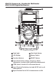
AM-510 Commercial / Residential Multimeter AM-510-EUR Digital Multimeter 1 2 3 4 6 5 10 7 9 8 1 Flash light 4 Flash light Button 2 LCD Display 5 Rotary Switch 3 Function Buttons 6 SELECT Button 7 Input Terminal for voltage, frequency, diode, capacitance, resistance and continuity measurement 8 COM (return) terminal for all measurements 9 Input Terminal for battery test and AC/DC mA or μA measurement 10 Input Terminal for AC/DC A measurement to10A
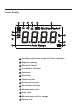
Screen Display 5 6 7 8 9 10 4 3 11 2 12 13 1 1 The Meter selects the range with best resolution 2 Negative reading 3 Alternate Current 4 Low battery indicator 5 Data hold 6 Diode test 7 Continuity test 8 Relative zero mode 9 Non-Contact Voltage 10 Measurement units 11 Duty Cycle 12 Measurement unit for voltage 13 Battery Test
AM-510 Commercial / Residential Multimeter AM-510-EUR Digital Multimeter CONTENTS SYMBOL..................................................................................................................2 SAFETY INFORMATION..........................................................................................2 UNPACKING AND INSPECTION..............................................................................3 FEATURES......................................................................................
SYMBOLS X � Caution ! Risk of electric shock. B Alternating Current (AC) F Direct Current (DC) T The equipment is protected by double insulation or reinforced insulation J Earth (Ground) Caution! Refer to the explanation in this Manual Audible tone M Battery � Complies with European Directives � Conforms to relevant Australian standards ) = Canadian Standards Association (NRTL/C) Do not dispose of this product as unsorted municipal waste. Contact a qualified recycler.
CENELEC Directives The instruments conform to CENELEC Low-voltage directive 2006/95/EC and Electromagnetic compatibility directive 2004/108/EC X�Warning: Read Before Using • To avoid possible electrical shock or personal injury, follow these instructions and use the Meter only as specified in this manual. • Do not use the Meter or test leads if they appear damaged, or if the Meter is not operating properly. If in doubt, have the Meter serviced. • Always use the proper function and range for measurements.
FEATURES The digital multimeter designed for advanced residential applications. Rewire an electrical panel, install heated floors or new light fixtures, troubleshoot and repair home appliances, electrical sockets and automotive electrical problems with this easy-to-use multimeter.
MAKING MEASUREMENT X� 1. Use the proper function and range for measurements. 2. To avoid possible electrical shock, personal injury or damages to the Meter, disconnect circuit power and discharge all high-voltage capacitors before testing resistance and diode. 3. Connecting test leads: • Connect the common (COM) test lead to the circuit before connecting the live lead; • After measurement, remove live lead before removing the common (COM) test lead from the circuit 4.
Display freezes present reading / press 2 sec to turn on LCD backlight. HOLD / REL Relative zero mode RANGE Manual or Auto range switching. The default setting is Auto ranging, press to switch to manual ranging (selectable resolutions). Press for 2 sec to return to auto ranging. Hz / % Frequency / Duty Cycle. Press to turn on Frequency measurement mode; press again for duty cycle measurement. Flash light Press to enable the function when at relevant rotary switch function.
Measuring AC and DC Current Press SELECT button to select AC or DC current measurement function. X�To avoid personal injury or damage to the Meter: 1. Do not attempt to make an in-circuit current measurement when the open-circuit potential to earth ground exceeding 600V. 2. Switch to proper function and range for your measurement. 3. Do not place the test probe in parallel with a circuit when the test leads are connected to the current terminals. 4.
AC/DC RL Auto Range /Manual Range RL Measuring Resistance X�Disconnect circuit power and discharge all high-voltage capacitors before testing resistance. R Note: On a higher resistance measurement (>1Me), the measurement may take a few seconds to get stable reading.
Measuring Continuity X�Disconnect circuit power and discharge all high-voltage capacitors before testing continuity. R 10 R 150 Measuring Diode X�Disconnect circuit power and discharge all high-voltage capacitors before testing diode.
Measuring Capacitance X�Disconnect circuit power and discharge all high-voltage capacitors before testing capacitance. C Auto Range Measuring Frequency Press Hz/% button to select Frequency / Duty Cycle measurement function. X�To avoid personal injury or damage to the Meter, do not apply voltage higher than 600V.
Non-Contact Voltage Sensing X� 1. To avoid personal injury or damage to the Meter, do not test on un-insulated high voltage wires. 2. Buzzer will sound when detecting voltage higher than AC 90V. Screen displays“OL”. 3. Do not test on hazardous live wires higher than AC 600V.
Battery Test X�Applying a voltage source or incorrect battery type under battery test may cause personal injury or damage to the Meter. Battery 1.5V range is for dry battery not exceeding 2Vdc. The resistance load is around 30Ω. Battery 9V range is for dry battery not exceeding 15Vdc. The resistance load is around 1KΩ. SPECIFICATION Ambient temperature: 23°C ±5°C (73.
Altitude: Operating ≤ 2000m Operating temperature: 0°C ~ +40°C (32°F ~ 104°F) Relative humidity: 0°C ~ +30°C (32°F ~ 86°F) ≤75%; +30°C ~ +40°C (86°F ~ 104°F) ≤50% Storage temperature: -10°C ~ +50°C (14°F ~ 122°F) Electromagnetic compatibility: In an RF filed of 1V/m = Specified accuracy ±5% Battery: 9V, 6F22, NEDA1604 or equivalent Low battery indication: Dimensions (L x W x H): 182 mm x 90 mm x 45 mm (7.2 in x 3.5 in x 1.8 in) Weight: Approx. 354g (0.78lb) with batteries installed 1.
3. Resistance Measurement Range Resolution Accuracy 400.0Ω 0.1Ω ±(1.2%+2dgt) 4.000kΩ 1Ω 40.00kΩ 10Ω 400.0kΩ 100Ω 4.000MΩ 1kΩ ±(1.2%+2dgt) 40.00MΩ 10kΩ ±(1.5%+5dgt) ±(1.0%+2dgt) 400Ω range: Measured value = (Measured display value) – (Short-circuiting value of probe) Open circuit voltage: around 0.5V Overload protection: 600Vrms 4. : Continuity Range G : Diode measurement Resolution Accuracy Open circuit voltage is around 0.5V. 0.1Ω G 1mV Resistance >150Ω, buzzer will not sound.
6. Measurement of frequency/duty cycle Range Resolution Accuracy 10Hz~10MHz 0.01Hz~0. 01MHz ±(0.1%+4dgt) 0.1%~99.9% 0.1% -- Overload protection: 600Vrm Input amplitude: (DC level is 0.) 10Hz~1MHz: 300mV ≤ a ≤30Vrms >1MHz~10MHz: 600mV ≤ a ≤30Vrms Input amplitude and frequency response must meet following conditions when reading frequency or duty cycle during AC voltage or current measurement • Input amplitude ≥ Range × 30% • Frequency response: ≤400Hz 7.
Overload protection: � mA /μA input: F1 fuse, 0.5A H 660V fast-fuse, F1 fuse, 0.5A H 700V fast-fuse, 10 A input: F2 fuse, 10A H 660V fast-fuse, F2 fuse, 10A H 600V fast-fuse, 6.3×32mm (AM-510) 6.3×32mm (AM-510-EUR) 6.3×32mm. (AM-510) 6.3×25mm. (AM-510-EUR) 9. AC Current Measurement Range μA mA A Resolution 400.0μA Accuracy 0.1μA 4000μA 1μA 40.00mA 10μA 400.0mA 0.1mA 4.000A 1mA 10.00A 10mA ±(1.2%+2dgt) ±(1.
MAINTENANCE AND REPAIR If the Meter fails to operate, check battery, test leads, etc., and replace as necessary. Double check the followings: 1. Replace the fuse or battery if the meter does not work. 2. Review the operating instructions for possible mitestledningers in operating procedure. Quick check on 0.5A FUSE: Step 1: Turn the rotary switch to Ω function. Step 2: Connect test lead to E/V/Ω/Hz terminal and mA/μA terminal.
Except for the replacement of the battery, repair of the meter should be performed only by a Factory Authorized Service Center or by other qualified instrument service personnel. The front panel and case can be cleaned with a mild solution of detergent and water. Apply sparingly with a soft cloth and allow to dry completely before using. Do not use aromatic hydrocarbons, Gasoline or chlorinated solvents for cleaning.
10 A input terminal: F2 fuse, 10A H 660V fast-fuse, 6.3×32mm. (AM-510) F2 fuse, 10A H 600V fast-fuse, 6.3×25mm.
Visit www.Amprobe.com for • • • • Catalog Application notes Product specifications User manuals Amprobe® www.Amprobe.com info@amprobe.com Everett, WA 98203 Tel: 877-AMPROBE (267-7623) Amprobe® Europe Beha-Amprobe In den Engematten 14 79286 Glottertal, Germany Tel.