
User Manual


6
11 Continuity.
12 Insulation resistance.
13 Loop impedance — Hi current trip mode
14 Loop impedance — No trip mode.
15 RCD tripping time.
16 RCD tripping level.
Volts
18 Phase rotation.
19 Earth resistance.
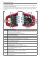
20 Rotary switch.
b
L
38
40
39
30
34 33
32
31
28
37
35
36
Comp
kA
V
Hz
29
27
24
26
25
23
21 22
21
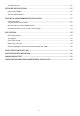
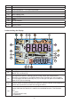
Displays the selected Memory mode. Memory modes are: Select (F1), Store (F2),
Recall (F3), or Clear (F4).
22
Configuration options. Settings you can make within the measurement
functions. For example, in the RCD Tripping Time function (
PT) you can press
F2 to multiply the test current by x1/2, x1, x5 and you can press F3 to select the
type of RCD you are testing.
23
Arrows above or below the terminal indicator symbol indicate reversed polarity.
Check the connection or check the wiring to correct.
24
Terminal indicator symbol. A terminal indicator symbol with a dot (O) in the
center indicates the terminal is used for the selected function. The terminals
are:
•L(Line)
•PE(ProtectiveEarth)
•N(Neutral)