
Modulizer User's Manual PRODSP1200P
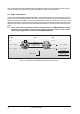
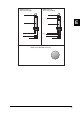

Table Of Contents
- TABLE OF CONTENTS
- 1. INTRODUCTION
- 1.1 The design concept
- 1.2 Before you begin
- 1.3 Control elements
- 1.3.1 Front panel control elements
- 1.3.2 Key combinations
- 1.3.3 Back panel
- 1.4 The effect algorithms
- 2. OPERATION
- 2.1 Effects structure
- 2.2 Selecting presets
- 2.3 Editing programs
- 2.4 Saving programs
- 2.5 MIDI control
- 2.5.1 "Modulation"-controller
- 3. APPLICATIONS
- 3.1 Level setting
- 3.2 Using the MODULIZER PRO in the aux bus
- 3.3 Using the MODULIZER PRO in the insert path
- 3.4 Using the MODULIZER PRO as an effects device for instruments
- 3.5 Using the MODULIZER PRO in a MIDI system
- 3.6 Saving data via MIDI
- 4. TECHNICAL BACKGROUND
- 4.1 Digital audio processing
- 4.2 Reverberation and reflection
- 4.3 Audio dynamics
- 4.3.1 Noise as a physical phenomenon
- 4.3.2 What are audio dynamics?
- 4.3.3 Compressors/limiters
- 4.3.4 Expanders/noise-gates
- 4.4 Artificial harmonics generation
- 4.5 Tube technology
- 5. INSTALLATION
- 5.1 Rack mounting
- 5.2 Mains connection
- 5.3 Audio connections
- 5.4 MIDI connections
- 5.5 Operating level switch
- 6. APPENDIX
- 6.1 Parameter overview
- 6.2 Variation table
- 6.3 MIDI implementation
- 6.4 Default settings
- 6.5 Preset parameters
- 6.6 Specifications
- 7. WARRANTY

34
with the identical type and rating. NEVER use fuses of different ratings or cover faulty fuses with aluminium foil.
This can cause fire and electric shocks and will endanger your life and the lives of others.
5.3 Audio connections
As standard, the BEHRINGER MODULIZERPRO is installed with electronically servo-balanced inputs and
outputs. The new circuit design features automatic hum and noise reduction for balanced signals and thus
allows for trouble-free operation, even at high operating levels. Externally induced mains hum etc. will be
effectively suppressed. The automatic servo-function recognizes the presence of unbalanced connectors and
adjusts the nominal level internally to avoid level differences between the input and output signals (correction
6dB).
+ Please ensure that only qualified persons install and operate the MODULIZERPRO. During
installation and operation the user must have sufficient electrical contact to earth. Electro-
static charges might affect the operation of the MODULIZERPRO!
1 2
3
2 1
3
Pin 1
Cable InputOutput
Pin 2 = (+) Signal Positive
Pin 3 = (-) Signal
Shield
(+) Signal + Hum
(-) Signal + Hum
Negative
(+)Hum + Signal
(-)Hum + Signal
2 x Signal
Ground
RFI and Hum
= Signal + 6 dB
Fig. 5.1: Compensation of interference with balanced connections
5. INSTALLATION