EPC TA100 AM Service & Maintenance Manual MAEN043, 2010-12 English
Foreword Service & Maintenance manual for EPC TA100 AM Foreword This manual contains detailed information about EPC TA100 AM, including descriptions of various actions that can be carried out in order to maintain or update the Panel PC hardware and software. The manual contains descriptions of basic maintenance and replacement of common parts in EPC TA100 AM. The following other manuals are available for EPC TA100 AM: EPC TA100 AM installation manual (MAEN040x) for information regarding installation.
Contents Contents 1 Safety Precautions ....................................................... 1.1 General ........................................................... 1.2 During Installation .............................................. 1.3 During Use ....................................................... 1.4 Service and Maintenance ........................................ 1.5 Dismantling and Scrapping ..................................... 2 Introduction ..................................................
Contents 10 Environmental Aspects ................................................. 36 10.1 General Environmental Aspects ................................ 36 10.2 Environmental Impact of the Panel PCs ........................ 36 10.2.1 10.2.2 10.3 10.4 Mechanical Components . . . . . . . . . . . . . . . . . . . . . . . . . . . . . . . . . . . . . . . . 36 Electronics . . . . . . . . . . . . . . . . . . . . . . . . . . . . . . . . . . . . . . . . . . . . . . . . . . . . . . .36 Recycling ................
Safety Precautions 1 Safety Precautions Both the installer and the owner and/or operator of the Panel PC must read and understand this installation manual. 1.1 • • • • • • • • • • • • General Read the safety precautions carefully. Check the delivery for transportation damage. If damage is found, notify the supplier as soon as possible. Do not use the Panel PC in an environment with high explosive hazards. The supplier is not responsible for modified, altered or reconstructed equipment.
Safety Precautions 1.3 • • • Keep the Panel PC clean. Emergency stop and other safety functions may not be controlled from the Panel PC. Do not use too much force or sharp objects when touching the keys, touch screen etc. 1.4 • • • • • Service and Maintenance Only qualified personnel should carry out repairs. The agreed warranty applies. Before carrying out any cleaning or maintenance operations, disconnect the equipment from the electrical supply.
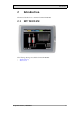
Introduction 2 Introduction This manual describes how to maintain the EPC TA100 AM. 2.
Introduction 2.2 Maintenance Carefully read the instructions before beginning maintenance on the Panel PC. • Only qualified personnel should carry out maintenance. • The agreed warranty and license agreements apply. • Any damage to the Panel PC caused by personnel invalidates the warranty. • Before carrying out any cleaning or maintenance operations, disconnect the Panel PC from the power supply. • Clean the display and surrounding front cover with a soft cloth and mild detergent.
Introduction 2.5 Contact and Support If you want to report a fault or have a question about the Panel PC, please contact your local supplier or fill out the form on the web site. 1. Enter the web site www.beijerelectronics.com and select Support. 2. Select Contact in the menu. Make sure to provide information about type number, serial number, environment and an installation description.
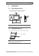
Installation 3 Installation 3.1 Space Requirements • • Installation plate thickness: 1.5 - 9.0 mm (0.06 - 0.35 inch) Space requirements when installing EPC TA100 AM: 100 mm (4.0 inch) 228 mm (8.98 inch) 50 mm (2.0 inch) 100 mm (4.0 inch) 50 mm (2.0 inch) 100 mm (4.0 inch) 58 mm (2.28 inch) 302 mm (11.89 inch) Caution: The openings on the enclosure are for air convection. Do not cover these openings. 3.2 Installation Process 1. Unpack and check the delivery.
Installation 2. Place the panel cut out where the Panel PC is to be situated, draw along the outer sides of the holes and cut according to the markings. 3. Secure the Panel PC in position, using all the fastening holes and the provided brackets and screws: x 13 0.5 - 1.
Installation 4. Connect the cables in the specified order, according to the drawing and steps below. Caution: • Ensure that the Panel PC and the controller system have the same electrical grounding (reference voltage level), otherwise errors in communication may occur. • The Panel PC must be brought to ambient temperature before it is started up. If condensation forms, ensure that the Panel PC is dry before connecting it to the power outlet.
Technical Data 4 Technical Data Parameter EPC TA100 AM Front panel, W x H x D 302 x 228 x 6 mm Mounting depth 58 mm (158 mm including clearance) Front panel seal IP 66 Rear panel seal IP 20 Keyboard material/Front panel Touch screen: Polyester on glass, 1 million finger touch operations. Overlay: Autotex F157 or F207*. Reverse side material Powder-coated aluminum Weight 2.
Chemical Resistance 5 Chemical Resistance 5.1 Metal Casing The frame and casing material is powder-coated aluminum.
Chemical Resistance 5.2 Touch Screen and Overlay 5.2.1 Autotex F157/207 Autotex F157 or F207 covers the overlay surrounding the touch screen.
Chemical Resistance 5.2.2 Touch Screen Surface The touch screen surface on the panel withstands exposure to the following solvents without visible change: Solvents Time Acetone 10 minutes Isopropanol 10 minutes Toluene 5 hours 5.2.3 Autoflex EB It is recommended to use the Autoflex EB touch display protection film, that can be ordered from Beijer Electronics. Solvent Resistance Autoflex EB withstands exposure to the same chemicals as Autotex F157 or F207 according to section Autotex F157/207.
Hardware Replacement 6 Hardware Replacement This section contains instructions on how to replace Panel PC hardware. Only components included in the latest bill of material and spare parts list are allowed. See Available Spare Parts for EPC TA100 AM. 6.1 Cables Most of the Panel PCs use the same type of flex cable connectors. connector flanges Flex cable connector To release the flex cables from the connector, gently push the two flanges on the cable connector towards the flex cable.
Hardware Replacement 6.2 Replacing the Rear Cover The following is needed: • A new rear cover, see Available Spare Parts for EPC TA100 AM • A torx T10 screwdriver Note: Make sure to use adequate ESD protection. Follow the steps below to replace the rear cover: 1. Power off the Panel PC. 2. Remove the rear cover of the Panel PC by loosening the 4 torx screws. 4 x torx screws 3. Re-assemble with the new rear cover in reverse order.
Hardware Replacement 6.3 Replacing the Display/Display Cable The following is needed: • A new display/display cable, see Available Spare Parts for EPC TA100 AM • A torx T10 screwdriver Note: Make sure to use adequate ESD protection. Follow the steps below to replace the display/display cable: 1. Power off the Panel PC. 2. Follow the instructions under Replacing the Rear Cover to remove the rear cover. 3.
Hardware Replacement 5. Remove the mounting plate (9 torx screws). Gently lift the mounting plate with the display and power card. 9 x torx screws 6. Flip the mounting plate and unscrew the 4 torx screws. 4 x torx screws 7. Re-assemble the panel in reverse order. 6.3.1 Calibrating the Touch Screen Follow the steps below to calibrate the touch screen: A touch calibration tool is pre-installed in the EPC TA100 AM. It can be started from the desktop icon or from the Start menu.
Hardware Replacement 1. Press the first calibration point until the Release message appears. Touch calibration point If you release the calibration point too early, an error message is displayed. 2. Touch the following nine touch calibration points as they appear on the screen, and release them as the Release messages appear. When touch calibration has been performed successfully, a confirmation is displayed.
Hardware Replacement 6.4 Replacing the Complete Front The following is needed: • A new front, see Available Spare Parts for EPC TA100 AM • A torx T10 screwdriver Note: Make sure to use adequate ESD protection. Follow the steps below to replace the complete front of the EPC TA100 AM: 1. Power off the Panel PC. 2. Follow the steps 1-3 and 5 in the Replacing the Display/Display Cable instructions, but in step 3, only disconnect the flex cables and the LED cable (do not remove the power card). 3.
Hardware Replacement 6.5 Replacing the Backlight Note: All lamps in the display must be replaced at the same time. The following is needed: • A new backlight, see Available Spare Parts for EPC TA100 AM • A torx T10 screwdriver Note: Make sure to use adequate ESD protection. Follow the steps below to replace the battery of the EPC TA100 AM: 1. First, follow the steps 1–5 in section Replacing the Rear Cover. 2.
Hardware Replacement 6.
Additional Installation Tips 7 Additional Installation Tips When experiencing communication problems in for example noisy environments or when operating close to temperature limits, the following recommendations are to be noticed. 7.
Additional Installation Tips 7.2 Ethernet Connection in the Panel PC Industrial Ethernet RJ45 RJ45 1 RJ45 RJ45 Panel PC RJ45 3 2 Panel PC RJ45 4 Shielded 1-1 2-2 3-3 Short and unshielded Panel PC RJ45 8-8 5 Panel PC RJ45 0.1 uF 250 V 5351 In some industrial units for Ethernet, the RJ45 contact’s shield is connected to the chassis via a capacitor, see 1 in drawing above. The Panel PC’s Ethernet shield is directly connected to the chassis, see 2 in drawing above. 1.
Additional Installation Tips 7.3 • • • • • • • • To Achieve Better EMC Protection Initially, use the original cabling from Beijer Electronics primarily. Use shielded cables for RS232 communication. Use twisted pair and shielded cabling for RS422 and RS485. Use the cabling intended for the bus type; Ethernet, Profibus, CC-Link, CAN, Device Net etc. Install and connect according to applicable specifications for the relevant bus standard.
Additional Installation Tips 7.4 Ambient Temperature The maximum ambient temperature for the Panel PC is provided in the specifications. The ambient temperature refers to the temperature in the device cabinet which cools the Panel PC’s electronics.
Additional Installation Tips 7.5 Safety Most of the Panel PCs are fed with 24 V DC. Power supply 230 V AC to 24 V DC Panel PC +24 V 1 0V 4 Power supply 230 V AC to 24 V DC Panel PC +24 V 2 0V 4 Distance? Power supply 230 V AC to 24 V DC Panel PC +24 V 3 0V 4 COM1 Small controller with expansion unit Ch0 Ch1 230 V AC COM100 Ch100 Ch101 5355 If you use a power supply that meets safety standards and only feeds the Panel PC, there is no problem. See 1 in drawing above.
Additional Installation Tips 7.6 Galvanic Isolation Internal electronic Filter Ethernet DC/DC galvanic isolation DC/AC VCC +24 V DC CFL 0 V (GND) 0V 1.5 m RS422/485 RS232 USB 5356 USB The Panel PC has galvanic isolation against the 24 V DC feed but no galvanic isolation between the communication ports for RS232, RS422/485 and USB. Only the Ethernet connection has galvanic isolation.
Additional Installation Tips 7.7 Cable and Bus Termination RS485 Use shielded and twisted pair cable. The pair capacitance may not exceed 52.5 pF/m and area at least 0.25 mm2 (AWG 24), if you want to use the maximum transfer distance and maximum transfer speed. 0 V, the reference voltage for communication should be included in the cabling. With two-way communication use two pairs; one pair for communication and one pair for 0 V. The shield must be grounded at one end.
Fault Tracing 8 Fault Tracing This section includes different fault scenarios and steps to follow to trace the fault. The EPC TA100 AM is not working properly, and the power LED is off 1. 2. 3. 4. 5. Is the power voltage correct? Does the power supply deliver enough current? Check the fuse. Check the power card. Is the power card correctly mounted? The EPC TA100 AM is not communicating 1. Check the communication cable between the units. 2. Check the communication ports on the CPU board.
Fault Tracing The touch screen is malfunctioning or is not responding at all 1. Re-calibrate the touch screen according to the Calibrating the Touch Screen section. 2. Check that the flex cable is correctly fitted. 3. Replace the display of the Panel PC according to the Replacing the Display/Display Cable section. 4. Check the touch interface on the power card. Lines in display have wrong color or the display picture is shifted 1.
Software 9 Software This chapter describes how to maintain and update the operating system in the EPC TA100 AM, and instructions about how to recover the operating system. 9.1 General Information about Software The EPC TA100 AM is delivered with an image (operating system) pre-stored in the Nand Flash memory. 9.1.
Software 9.2 Update or Customize Software A customized operating system image can be developed with the needs of the customer. In this case, please contact Beijer Electronics sales office for detailed information. 9.2.1 Backup and Recovery It is important to generate a backup image of the operating system. In case of emergency, a recovery can be done in minutes using a backup image. Several programs on the market are suitable for this.
Environmental Aspects 10 Environmental Aspects This chapter includes information about the environmental impact of the EPC TA100 AM. More information can be found on the manufacturer’s web site. 10.1 General Environmental Aspects The manufacturer’s activities meet internal requirements as well as those of the SS-EN ISO 9001:2000 and SS-EN ISO 14001:2004 international standards. 10.2 Environmental Impact of the Panel PCs 10.2.
Environmental Aspects 10.3 Recycling The Panel PCs consist largely of aluminum. It is a great advantage in terms of both resources and the environment if it can be recycled. Make sure that Panel PCs taken out of service are sent to facilities for electronic scrap. The manufacturer’s electronic waste is recycled by Stena Technoworld AB. Aluminum front/rear casings and other covers can be removed and recycled. Plastic display frames and CF covers must be recycled as hard plastic.
Head office Beijer Electronics AB Box 426 201 24 Malmö, Sweden www.beijerelectronics.