iX Panel TA100 Installation Manual MAEN010A, 2010-12 English
Foreword Installation manual for iX Panel TA100 Foreword All iX Panels are developed to satisfy the demands of human-machine communication. Built-in functions such as displaying and controlling text, dynamic indication, time channels, alarm and recipe handling are included. The operator panel works primarily in an object-oriented way, making it easy to understand and use. Configuration is carried out on a PC using the iX Developer configuration tool.
Contents Contents 1 Safety Precautions ....................................................... 1.1 General ........................................................... 1.2 During Installation .............................................. 1.3 During Use ....................................................... 1.4 Service and Maintenance ........................................ 1.5 Dismantling and Scrapping ..................................... 2 Installation ..................................................
Safety Precautions 1 Safety Precautions Both the installer and the owner and/or operator of the operator panel must read and understand this installation manual. 1.1 • • • • • • • • • • • • General Read the safety precautions carefully. Check the delivery for transportation damage. If damage is found, notify the supplier as soon as possible. Do not use the operator panel in an environment with high explosive hazards. The supplier is not responsible for modified, altered or reconstructed equipment.
Safety Precautions 1.3 • • • Keep the operator panel clean. Emergency stop and other safety functions may not be controlled from the operator panel. Do not use too much force or sharp objects when touching the keys, touch screen etc. 1.4 • • • • • • Service and Maintenance Only qualified personnel should carry out repairs. The agreed warranty applies. Before carrying out any cleaning or maintenance operations, disconnect the equipment from the electrical supply.
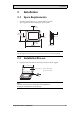
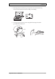
Installation 2 Installation 2.1 Space Requirements • • Installation plate thickness: 1.5 - 9.0 mm (0.06 - 0.35 inch) Space requirements when installing the operator panel: 100 mm (4.0 inch) 228 mm (8.98 inch) 50 mm (2.0 inch) 100 mm (4.0 inch) 50 mm (2.0 inch) 100 mm (4.0 inch) 58 mm (2.28 inch) 302 mm (11.89 inch) Caution: The openings on the enclosure are for air convection. Do not cover these openings. 2.2 Installation Process 1. Unpack and check the delivery.
Installation 2. Place the panel cut out where the operator panel is to be situated, draw along the outer sides of the holes and cut according to the markings. 3. Secure the operator panel in position, using all the fastening holes and the provided brackets and screws: x 13 0.5 - 1.
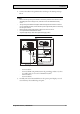
Installation 4. Connect the cables in the specified order, according to the drawing and steps below. Caution: • Ensure that the operator panel and the controller system have the same electrical grounding (reference voltage level), otherwise errors in communication may occur. • The operator panel must be brought to ambient temperature before it is started up. If condensation forms, ensure that the operator panel is dry before connecting it to the power outlet.
Installation 2.2.1 Mode Switches All mode switches must be in OFF position during operator panel use. The mode switches should not be touched unless by qualified personnel. ON DIP 1 2 3 4 MODE EXPANSION ON DIP 1 2 3 4 MODE CF CARD BUSY 1 24V DC COM 2 RS232 10/100 COM 1 RS422 RS485 2.2.2 Connections to the Controller For information about the cables to be used when connecting the operator panel to the controller, please refer to the help file for the driver in question. 2.2.
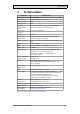
Technical Data 3 Technical Data Parameter iX Panel TA100 Front panel, W x H x D 302 x 228 x 6 mm Mounting depth 58 mm (158 mm including clearance) Front panel seal IP 66 Rear panel seal IP 20 Keyboard material/Front panel Touch screen: Polyester on glass, 1 million finger touch operations. Overlay: Autotex F157 or F207*. Reverse side material Powder-coated aluminum Weight 2.
Chemical Resistance 4 Chemical Resistance 4.1 Metal Casing The frame and casing material is powder-coated aluminum.
Chemical Resistance 4.2 Touch Screen and Overlay 4.2.1 Autotex F157/207 Autotex F157 or F207 covers the overlay surrounding the touch screen.
Chemical Resistance 4.2.2 Touch Screen Surface The touch screen surface on the panel withstands exposure to the following solvents without visible change: Solvents Time Acetone 10 minutes Isopropanol 10 minutes Toluene 5 hours 4.2.3 Autoflex EB It is recommended to use the Autoflex EB touch display protection film, that can be ordered from Beijer Electronics. Solvent Resistance Autoflex EB withstands exposure to the same chemicals as Autotex F157 or F207 according to section Autotex F157/207.
Operator Panel Drawings 5 Operator Panel Drawings 5.
Beijer Electronics, MAEN010A 13 204 25 263 14 6 58 USB Host max 9 mm material thickness Ethernet COM2 RS232 302 Ethernet COM1 RS422/485 5.
Additional Installation Tips 6 Additional Installation Tips When experiencing communication problems in for example noisy environments or when operating close to temperature limits, the following recommendations are to be noticed. 6.
Additional Installation Tips 6.2 Ethernet Connection in the Panel Industrial Ethernet RJ45 RJ45 1 RJ45 RJ45 Operator panel RJ45 3 2 Operator panel RJ45 4 Shielded 1-1 2-2 3-3 Short and unshielded Operator panel RJ45 8-8 5 Operator panel RJ45 0.1 uF 250 V 5351 In some industrial units for Ethernet, the RJ45 contact’s shield is connected to the chassis via a capacitor, see 1 in drawing above. The operator panel’s Ethernet shield is directly connected to the chassis, see 2 in drawing above. 1.
Additional Installation Tips 6.3 • • • • • • • • To Achieve Better EMC Protection Initially, use the original cabling from Beijer Electronics primarily. Use shielded cables for RS232 communication. Use twisted pair and shielded cabling for RS422 and RS485. Use the cabling intended for the bus type; Ethernet, Profibus, CC-Link, CAN, Device Net etc. Install and connect according to applicable specifications for the relevant bus standard.
Additional Installation Tips 6.4 Ambient Temperature The maximum ambient temperature for the operator panel is provided in the specifications. The ambient temperature refers to the temperature in the device cabinet which cools the panel’s electronics.
Additional Installation Tips 6.5 Safety Most of the operator panels are fed with 24 V DC. Power supply 230 V AC to 24 V DC Operator panel +24 V 1 0V 4 Power supply 230 V AC to 24 V DC Operator panel +24 V 2 0V 4 Distance? Power supply 230 V AC to 24 V DC Operator panel +24 V 3 0V 4 COM1 Small controller with expansion unit Ch0 Ch1 230 V AC COM100 Ch100 Ch101 5355 If you use a power supply that meets safety standards and only feeds the operator panel, there is no problem.
Additional Installation Tips 6.6 Galvanic Isolation Internal electronic Filter Ethernet DC/DC galvanic isolation DC/AC VCC +24 V DC CFL 0 V (GND) 0V 1.5 m RS422/485 RS232 USB 5356 USB The operator panel has galvanic isolation against the 24 V DC feed but no galvanic isolation between the communication ports for RS232, RS422/485 and USB. Only the Ethernet connection has galvanic isolation.
Additional Installation Tips 6.7 Cable and Bus Termination RS485 Use shielded and twisted pair cable. The pair capacitance may not exceed 52.5 pF/m and area at least 0.25 mm2 (AWG 24), if you want to use the maximum transfer distance and maximum transfer speed. 0 V, the reference voltage for communication should be included in the cabling. With two-way communication use two pairs; one pair for communication and one pair for 0 V. The shield must be grounded at one end.
Head office Beijer Electronics AB Box 426 201 24 Malmö, Sweden www.beijerelectronics.