iX T12B Installation Manual MAEN096C, 2013-09 English
Foreword Installation manual for iX T12B Foreword All operator panels are developed to satisfy the demands of human-machine communication. Built-in functions such as displaying and controlling text, dynamic indication, time channels, alarm and recipe handling are included. The operator panel works primarily in an object-oriented way, making it easy to understand and use. Configuration is carried out on a PC using the iX Developer configuration tool.
Contents Contents 1 Safety Precautions ....................................................... 1.1 General ........................................................... 1.2 UL and cUL Installation ......................................... 1.3 During Installation .............................................. 1.4 During Use ....................................................... 1.5 Service and Maintenance ........................................ 1.6 Dismantling and Scrapping .................................
Safety Precautions 1 Safety Precautions Both the installer and the owner and/or operator of the operator panel must read and understand this installation manual. 1.1 • • • • • • • • • • • • • Read the safety precautions carefully. Check the delivery for transportation damage. If damage is found, notify the supplier as soon as possible. Do not use the operator panel in an environment with high explosive hazards. The supplier is not responsible for modified, altered or reconstructed equipment.
Safety Precautions • For Canada also AVERTISSEMENT – AVANT DE DECONNECTER L’EQUIPEMENT, COUPER LE COURANT OUS’ASSURER QUE L‘EMPLACEMENT EST DESIGNE NON DANGEREUX. Warning: Only UL and cUL approved expansion units are allowed to be connected to the port designated “EXPANSION”. At the moment there are no such units evaluated or allowed. Warning: Do not replace expansion unit unless power has been switched off or the area is known to be non-hazardous.
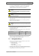
Safety Precautions • • • Separate the high voltage, signal and supply cables. Make sure that the voltage and polarity of the power source is correct before connecting the product to the power outlet. Peripheral equipment must be appropriate for the application and location. 1.4 • • • Keep the operator panel clean. Emergency stop and other safety functions may not be controlled from the operator panel. Do not use too much force or sharp objects when touching the keys, touchscreen etc. 1.
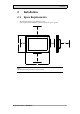
Installation 2 Installation 2.1 Space Requirements Maximum installation plate thickness: 8 mm Space requirements in millimeters when installing the operator panel: 50 50 100 100 242 100 • • 340 Note: The dimensions on the drawing are not proportional.
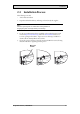
Installation 2.2 Installation Process The following is needed: • A Torx TX7 screwdriver 1. Unpack and check the delivery. If damage is found, notify the supplier. Note: Place the operator panel on a stable surface during installation. Dropping the panel or letting it fall may cause damage. 2. Use the cut out dimensions that are included on the outline drawing, found in section Operator Panel Drawings and in the Technical Data table, to cut a correct opening in the cabinet.
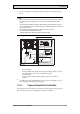
Installation 4. Connect the cables in the specified order, according to the drawing and steps below. Caution: • Ensure that the operator panel and the controller system have the same electrical grounding (reference voltage level), otherwise errors in communication may occur. • The operator panel must be brought to ambient temperature before it is started up. If condensation forms, ensure that the operator panel is dry before connecting it to the power outlet.
Installation 2.2.2 Other Connections and Peripherals Cables, peripheral equipment and accessories must be suitable for the application and its environment. For further details or recommendations, please refer to the supplier.
Technical Data 3 Technical Data Parameter iX T12B Front panel, W × H × D 340 × 242 × 79 mm Cut out dimensions, W×H 324 × 226 mm Mounting depth 72 mm (172 mm including clearance) Standalone mounting VESA 75 × 75 Note: Maximum screw length for VESA mounting is 4 mm. Usage of longer screws may lead to damage. Front panel seal IP 65 Rear panel seal IP 20 Touch screen material Polyester on glass, resistive. Overlay: Autoflex EBA 180L(1).
Technical Data Parameter iX T12B Operating temperature -10 °C – +50 °C Storage temperature -20 °C – +70 °C Relative humidity 5% – 85% non-condensed Approvals and certifications Information is available on the web site www.beijerelectronics.com (1) See section Chemical Resistance for more information.
Chemical Resistance 4 Chemical Resistance 4.1 Metal Casing The frame and casing material is powder-coated aluminum.
Chemical Resistance 4.2 Touch Screen and Overlay 4.2.1 Autoflex EBA 180L Autoflex EBA 180L covers the overlay surrounding the touch screen.
Chemical Resistance 4.2.2 Touch Screen Surface The touch screen surface on the operator panel withstands exposure to the following solvents without visible change: Solvents Time Acetone 10 minutes Isopropanol 10 minutes Toluene 5 hours 4.2.3 Autoflex EBA 180L It is recommended to use the Autoflex EBA 180Ltouch display protection film, that can be ordered from Beijer Electronics.
Operator Panel Drawings 5 Operator Panel Drawings 5.1 Connectors 1 Pos. 2 3 4 5 6 7 Connector Description 1 Power supply +24 V DC (18-32 V DC) 2 COM 1/2 Communication Ports 3 LAN (Port 2) 1 × 10/100 Base-T (shielded RJ-45) 4 USB 2 × USB Host 2.0, max output current 500 mA 5 Headphone Headphone Connector 6 LAN (Port 1) 1 × 10/100/1000 Base-T (shielded RJ-45) 7 COM 3/4 Communication Ports 5.
Operator Panel Drawings 5.3 iX T12B Outline 242 340 max. 8 mm 50 7 9 224 9 9 322 9 Note: A Step CAD file is available on the web site www.beijerelectronics.
Additional Installation Tips 6 Additional Installation Tips When experiencing communication problems in for example noisy environments or when operating close to temperature limits, the following recommendations are to be noticed. 6.
Additional Installation Tips Note: The grounding wires should be short and the conductor should have a large area. A long, thin grounding wire has a very high impedance (resistance) at high frequencies and will not guide disturbances to the ground. Multi-wire conductors are better than single wire conductors with the same area. A braided conductor wire with the same area is even better. The best is a short, thick grounding braid. 6.
Additional Installation Tips A good solution may be to use a shielded Ethernet cable, but to connect the shield at one end only. One option is to break the shield, see 3 in drawing above. A more elegant method is to expand the shielded Ethernet cabling with a piece of unshielded Ethernet cable, see 4 in drawing above. The shield can be grounded via an external 0.1 μF/250 V plastic capacitor, see 5 in drawing above. This will connect the HF transients to ground.
Additional Installation Tips 6.3 • • • • • • • • To Achieve Better EMC Protection Initially, use the original cabling from Beijer Electronics primarily. Use shielded cables for RS232 communication. Use twisted pair and shielded cabling for RS422 and RS485. Use the cabling intended for the bus type; Ethernet, Profibus, CC-Link, CAN, Device Net etc. Install and connect according to applicable specifications for the relevant bus standard.
Additional Installation Tips 6.4 Ambient Temperature The maximum ambient temperature for the operator panel is provided in the specifications. The ambient temperature refers to the temperature in the device cabinet which cools the operator panel’s electronics.
Additional Installation Tips 6.5 Safety Most of the operator panels are fed with 24 V DC. Power supply 230 V AC to 24 V DC Operator panel +24 V 1 0V 4 Power supply 230 V AC to 24 V DC Operator panel +24 V 2 0V 4 Distance? Power supply 230 V AC to 24 V DC Operator panel +24 V 3 0V 4 COM1 Small controller with expansion unit Ch0 Ch1 230 V AC COM100 Ch100 Ch101 5355 If a power supply that meets safety standards is used and only feeds the operator panel, there is no problem.
Additional Installation Tips 6.6 Galvanic Isolation Internal electronic Ethernet DC/DC galvanic isolation Filter DC/AC VCC +24 V DC CFL 0 V (GND) 0V 1.5 m RS422/485 RS232 USB USB The operator panel has galvanic isolation against the 24 V DC feed but no galvanic isolation between the communication ports for RS232, RS422/485 and USB. Only the Ethernet connection has galvanic isolation.
Additional Installation Tips 6.7 • • • Cable and Bus Termination RS485 If maximum transfer distance and maximum transfer speed is needed, shielded and twisted pair cable should be used. The mutual capacitance may not exceed 52.5 pF/m, and the cable area should be at least 0.25 mm2 (AWG 24). 0 V, the reference voltage for communication should be included in the cabling. With two-way communication use two pairs; one pair for communication and one pair for 0 V. The shield must be grounded at one end.
Head office Beijer Electronics AB Box 426 201 24 Malmö, Sweden www.beijerelectronics.