
Owner's manual


Installation
4.
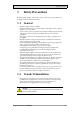
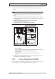
Connect the cables in the specified order, according to the drawing and steps
below.
Caution:
• Ensurethattheoperatorpanelandthecontrollersystemhavethesameelectrical
grounding(referencevoltagelevel),otherwiseerrorsincom municationmay
occur.
• Theoperatorpanelmustbebroughttoambienttemperaturebeforeitisstarted
up. Ifcondensationforms,ensurethattheoperatorpanelisdrybeforeconnecting
ittothepoweroutlet.
• Ensurethatthevoltageandpolarityofthepowersourceiscorrect.
• Useonlyshieldedcommunicationcables.
• Separatehighvoltagecablesfromsignalandsupplycables.
24V DC
RS232/
RS422/
RS485
24V DC
A
D
Controller
Power
B
Ethernet
C
– Connect cable A.
– Connect cable B, using an M5 screw and a grounding conductor (as short
as possible) with a cross-section of minimum 2.5 mm
2
.
– Connect cable C.
– Connect cable D. The recommended cross-section of the cable is
1.5 mm
2
.
5.
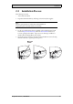
Carefully remove the laminated film over the operator panel display, to avoid
static electricity that could damage the panel.
2.2.1 Connectionstot
heController
For information about the cables to be used when connecting the operator panel to
the controller, please refer to the help file for the driver in question.
BeijerElectronics, MAEN096C
9