Dishwasher User manual DDS25841X DIS25841 DDS25842X DIS25842 USA Document Number : 15 9302 0100_BA_BEKO45_USA/ 06-09-18.
Dishwasher User manual DDS25841X DIS25841 DDS25842X DIS25842 USA Document Number : 15 9302 0100_BA_BEKO45_USA/ 06-09-18.
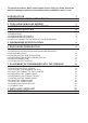
To prevent accidents, which could cause serious injury or death, as well as machine damage read these instructions before installation and / or use. INTRODUCTION 1. IMPORTANT SAFETY INSTRUCTIONS 1 1 2. TOOLS WHICH MAY BE NEEDED 3. MATERIALS WHICH MAY BE NEEDED 4. MATERIALS SUPPLIED 3 3 4 5. DISHWASHER SPECIFICATIONS 5 6. ENCLOSURE PREPARATION 6 1.1 INSPECT THE DISHWASHER 4.1 PARTS SUPPLIED 4.2 MANUAL BAG 4.3 DISHWASHER PARTS BAG 1 4.4 DISHWASHER PARTS BAG 2 4.
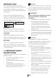
INTRODUCTION NOTICE : Please read this installation manual and particularly the safety instructions completely and carefully. They will save you time and effort and help to ensure optimum dishwasher performance. Read these installation instructions completely before installing and follow them carefully. Save these installation instructions and pass them on to any future user. Be sure to observe all listed warnings and cautions. Look particularly for the icons with exclamation marks inside.
•• •• •• •• •• •• NOTICE : ruptures that occur as a result of freezing are not covered by warranty. Dishwasher must be secured to adjacent cabinetry using the brackets provided. Failure to do this may cause damage to property or bodily injury. Connect to a properly rated, protected and sized power supply circuit to avoid electrical overload.
2. TOOLS WHICH MAY BE NEEDED 3. MATERIALS WHICH MAY BE NEEDED (Additional materials may be required to comply with local codes) Hot Water Supply Line - Minimum 3/8” O.D. copper tubing or metal braided dishwasher supply line. Elbow with 3/4” N.P.T. female thread for dishwasher side, and sized to fit your water supply line (copper tubing/compression fitting, or braided hose) on the other side. Dishwasher connection is 3/4" male. UL listed conduit connector or strain relief.
4. MATERIALS SUPPLIED 4.1 PARTS SUPPLIED 4.2 MANUAL BAG The dishwasher comes with a manual bag containing: •• User manual, •• Installation manual v. x4 x2 x. Parts for your dishwasher will come in several plastic bags. Check your parts bags shown to make sure you have all the parts as listed to the left. 4.
5. DISHWASHER SPECIFICATIONS 5.1 TECHNICAL FEATURES Permissible water pressure Electrical connection Total power Heater power 4.35 - 145 psi (0.3 - 10 bars) 120 V (volts), 12 A (amps), 60Hz (hertz) 1400 W (watts) 1100 W (watts) NOTICE : Because we continually strive to improve our products, we may change our specifications and design without prior notice. This device corresponds to the following directives: UL 749 Household Dishwasher directive.
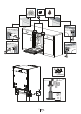
6. ENCLOSURE PREPARATION 6.1 ELECTRICAL PREPARATION WARNING The dishwasher is designed for an electrical supply of 120 V, 60 Hz, AC, connected to a dishwasher-dedicated, properly grounded electrical circuit with a fuse or breaker rated for 15 amperes. 6.
d) ? j + 50 max 50 (+50mm) 7 USA
WARNING Dishwasher must be secured to adjacent cabinetry using the mounting brackets provided. Failure to do this may cause damage to property or bodily injury. Place the two mounting brackets into the top corners of the dishwasher. Fix the mounting brackets (A) to the top corners of the dishwasher, with the screws supplied. Bend sides of mounting brackets (B) in order to fix from sides (if necessary). 6.
NOTICE : •• •• •• Make sure the dishwasher is plumb and notice dishwasher can be placed with a small clearance under the counter top. Turning the screwdriver in the direction of the black arrows will bring the dishwasher back feet up. Turning the screwdriver in the direction of the white arrows will take the dishwasher rear feet down. 6.4 INSTALLING THE SIDE TRIM STRIPS Remove the adhesive tape (Figure A). Place the trim strips on the front edge of the side walls (Figure B).
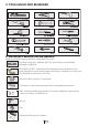
6.6 DRAIN PREPARATION The dishwasher drain hose may be connected to the drain plumbing in one of three ways (Figure A, B, C). NOTICE : •• •• •• •• Either one of the above methods must be used or the dishwasher will not operate properly. A hose that attaches to a sink spray can burst if it is installed on the same water line as the dishwasher. If your sink has one, it is recommended that the hose be disconnected and the hole plugged. The total length of the drain hose is 763/4” (1950mm).
6.7 STEAM PROTECTION FOIL Steam will form inside the dishwasher during operation. At the end of the cycle, when the dishwasher door is opened, it is required to use a steam protection foil to prevent any steam from collecting on the underside of the counter top. 6.6.2 FITTING THE PROTECTION FOIL Before applying the steam protection foil to the underside of the countertop, clean the area with a damp cloth (as shown in Figure A). Once the area dries, apply the steam protection foil.
7. PLACEMENT OF DISHWASHER INTO THE OPENING Now place the dishwasher into the opening and get ready to connect all hoses and electrical connections. CAUTION Make sure all hoses are pulled through the side opening of the cabinet, no hoses are kinked and all slack is taken out as shown in the above figure. 7.1 DRAIN HOSE CONNECTION, WATER SUPPLY & ELECTRICAL CONNECTIONS 7.1.1 DRAIN HOSE CONNECTION Connect the drain hose to the drain plumbing. 1.
Note that the marks on the rubber connection hose should be on the drain hose side •• 7.1.2 WATER SUPPLY CONNECTION Water supply may be connected to the dishwasher in one of two ways: •• With metal braided hose. •• With copper tubing. •• CAUTION •• •• •• •• Hot water supply line: Use minimum 3/8” O.D. copper tubing or metal braided dishwasher supply line.
7.2 READJUSTING FOOT LEVELS Now that the dishwasher is in the cabinet you must readjust the feet to bring the dishwasher up to the required height and attach it underneath the countertop. 1. Readjust the front foot levels with adjusting wrench to balance the dishwasher and raise it up under the countertop, make sure the unit is level. 2. Readjust the rear foot levels with a screwdriver to balance the dishwasher and raise it to the required height using the brackets supplied. 3.
Lock the toe kick brackets as shown with the plastic tab in the figure C by pushing the plastic tab on the dishwasher into the teeth of the bracket (C). 3. Now attach the toe kick to the bracket with the two (Ø 3/16” x 1/ ” - Ø 4mm x 6mm) screws and the caps provided as follows. 4 If the enclosure height is below 331/16” (840mm) use only “o” labelled toe kick (toe kick without slots). Installation should be done following the steps illustrated in the Figures A, B and C respectively. 1.
7.
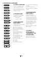
7.5 PREPARING THE TIMBER DOOR X o) X =? s) = = = = Mid. Point Mid. Point n) t) Weight (max) 5.
7.
7.7 INSTALLING THE TIMBER DOOR 4 1 3 2 7.
7.9 FIXING THE TIMBER DOOR (yy) Ø 4 x 43mm 12 34 5 1 23 45 7.10 ADJUSTING THE KICK PLATE • Check whether the bottom of the door hits the toe kick of the kitchen cabinet (A). • If the door hits the toe kick cut the necessary section out of the toe kick (B). • Apply silicon or sealant to the cut edge of the kitchen cabinet toe kick or paint so it does not absorb moisture.
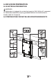
NOTICE : If you have a European kitchen or want to install a wooden toe kick to match your kitchen, please refer to one of the two drawings given below. Follow the same instructions on the brackets as for the removable toe kick. Installation should be done following the steps illustrated in the figures A, B, C, D respectively. NOTICE : The installer is responsible for the dishwasher installation.
4 ~ 1500 ~ 1800 ~ 2000 min 300 min 500 max 1000 1 1 2 2 1 1 22 2 USA min 300 2 min 120 max 1000 3 min 500 max 1000 7.
8. INSTALLER CHECKLIST Your installer must have completed and checked the following: •• The dishwasher is square and level. •• The dishwasher is fastened securely to the cabinetry. •• The dishwasher door opens and closes freely. The dishwasher door must close without hitting any cabinetry or counter top. •• The inlet water supply is turned on and checked for leaks. •• The drain hose has been connected and checked for leaks. There must be no kinks or obstructions in the drain hose.