
User Guide
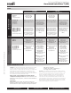
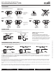
Table Of Contents

800-543-9038 USA 866-805-7089 CANADA 203-791-8396 LATIN AMERICA
6
FLOW PATTERNS
2-way Characterized Control Valves™ (Belimo B2 Series)
(Belimo B6 Series)
Two-way valves
should be installed
with the disc
upstream.
Flow direction
3-way Characterized Control Valves™ (Belimo B3 Series)
MIXING
DIVERTING
The A-port must
be piped to the coil
to maintain proper
control.
INCORRECT PIPING
The A-port must be piped to the coil to maintain proper control.
Coil
Return
Three-Way Mixing Valve Piping Diagram
(2 Inputs, 1 Output)
A
B
AB
Supply
Coi
l
Return
Three-Way Diverting Valve Piping Diagram
(1 Input, 2 Outputs)
A
B
AB
Supply
Coil
Return
Three-Way Mixing Valve Piping Diagram
(2 Inputs, 1 Output)
A
B
AB
Supply
Coi
l
Return
Three-Way Diverting Valve Piping Diagram
(1 Input, 2 Outputs)
A
B
AB
Supply
WARNING! Do Not Pipe in this manner!
Note Valve Porting!
The A-port must be piped to the coil! Not the B-port!
Flow is not possible from A to B. If AB-port is not piped as
the common port, the valve must be re-piped. It is good
practice to install a balancing valve in the bypass line. These
valves are intended for closed loop systems. Do not install
in an open loop system or in an application that is open to
atmospheric pressure.
OPERATION/INSTALLATION – CORRECT PIPING
2-way valves should be installed with the disc upstream. If installed with disc downstream, flow curve will be deeper. If installed “backwards” it is NOT necessary to
remove and change. No damage or control problems will occur.
3-WAY VALVES MUST BE PIPED CORRECTLY. They can be mixing or diverting. Mixing is the preferred piping arrangement.
The BELIMO Characterized Control Valve is a CONTROL valve, not a manual valve adapted for actuation. The control port is the A-port. It is similar to the globe valve in that
the middle port is the B or bypass port. The common port AB is on the main opposite the A-port. These diagrams are for typical applications only. Consult engineering
specification and drawings for particular circumstances.
REDUCED B-PORT FLOW
Note: The B-port flow of the 3-way CCV is lower than that of the A-port. In most applications this is beneficial since the reduced flow compensates for the inexistent
pressure drop across the coil in the bypass mode. Therefore, proper sizing is important to avoid flow noise in particular when the system is designed with constant
speed pumps. Please refer to our valve sizing and selection guidelines.
The flow velocity in the pipe upstream and downstream of the valve should be considered as well. The typical HVAC design maximum flow is 4 to 8 ft/s to avoid noise
issues.
Also, the pipe reduction factor must be considered and can be found on pages 3 and 4. Pipe reducers decrease the C
v
value of a valve and consequently increase the
pressure drop across the valve, a situation that could lead to noise or a lower than designed flow.
Flow, Operation and Installation
Characterized Control Valves™ (CCV)
K20903 - 04/08 - Subject to change. © Belimo Aircontrols (USA), Inc.