
Install Instructions


5
Tech.Doc - 03/21 - Subject to change. © Belimo Aircontrols (USA), Inc.
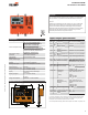
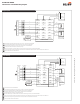
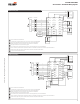
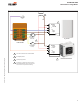
Input/Output Specifications
Type
Name
Description
Electrical Specifi cation
Input
R
Supply Hot
AC 24 V, ± 20%, 50/60Hz
Input
G/
OCC
Fan Signal (occupied)
On/Off, AC 24 V, ± 20%, 50/60Hz
Input
C
Supply Common
Common
Input
Y1
Cooling requirement
Stage 1
On/Off, AC 24 V, ± 20%, 50/60Hz
Input
Y2
Cooling requirement
Stage 2
On/Off, AC 24 V, ± 20%, 50/60Hz
Input
W1/
O/B
Heating requirement
Stage 1
On/Off, AC 24 V, ± 20%, 50/60Hz
Input
SAT ±
Supply Air Temperature
Sensor
Type: 10K NTC (Type II thermistor)
Input
OAT ±
Outdoor Air Temperature
Type: 10K NTC (Type II thermistor)
Type: 10K NTC (Type II thermistor)
Input
OAH ±
Outdoor Air Humidity
DC 0...10 V
Auto Detection: Sensor present if
voltage 0.5...10 V
Input
RAT ±
Return Air Temperature
Type: 10K NTC (Type II thermistor)
Type: 10K NTC (Type II thermistor)
Input
RAH ±
Return Air Humidity
DC 0...10 V
Auto Detection: Sensor present if
voltage 0.5...10V
Output
CC1
Compressor 1
RTU Stage 1
Mechanical Cooling
Circuitry
100'000 cycles @ inrush current
of 3A, normal current 1.5A
Impedance for Auto detection
@ 24 V:
<60O
Ω
@ 60Hz
<80O
Ω
@ 50Hz
@ 50Hz
Output
CC2
Compressor 2
RTU Stage 2
Mechanical Cooling
Circuitry
100'000 cycles @ inrush current
of 3A, normal current 1.5A
Impedance for Auto detection
@ 24 V:
<60O
Ω
@ 60Hz
<80O
Ω
@ 50Hz
@ 50Hz
Output
Act 1
Actuator supply common
Common
Output
Act 2
Actuator supply hot
AC 24 V, 50/60Hz
Output
Act 3
Actuator control output
DC 2...10 V
Input
Act 5
Actuator feedback
signal
DC 2...10 V
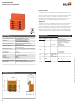
Installation
You can mount the ZIP Economizer in any orientation; it is recommended
that you mount it in a position that will allow full utilization of the LCD
and key pad and proper clearance for installation, servicing, wiring, and
removal.
Take the overall dimensions of 6.63" [168.5] x 7.12" [181] x 2" [50.8] and
mount in the interior of the RTU in a convenient location that you can
access. Secure the ZIP utilizing #8 self-tapping screws (included). A
minumum of two tabs need to be secured, one which is a top tab. Ideally
secure all four tabs. Wire the electrical connection using ¼” female
insulated spade connectors to prevent corrosion.
Technical Data
Power supply
AC 24 V ± 20%, 50/60 Hz; Class 2 power source
Power consumption rating*
4 VA base control (ECON-ZIP-BASE)
4 VA base control (ECON-ZIP-BASE)
5.5 VA base control with Energy Module
(ECON-ZIP-BASE + ECON-ZIP-EM)
(ECON-ZIP-BASE + ECON-ZIP-EM)
5 VA base control with Communication
Module (ECON-ZIP-BASE + ECON-ZIP-COM)
Module (ECON-ZIP-BASE + ECON-ZIP-COM)
6.5 VA base with Energy Module and
Communication Module. (ECON-ZIP-BASE +
ECON-ZIP-EM + ECON-ZIP-COM)
ECON-ZIP-EM + ECON-ZIP-COM)
Rated impulse voltage
330 V
Connectors
¼” male spade connectors
Environmental
RoHS, conformally coated
Software class
A
Control pollution degree
3
Temperature input signal
NTC 10k
Ω,
Type II
Humidity
5 to 95% RH non-condensing
Humidity input signal
DC 0...10 V; corresponds to 0...100%
Housing
NEMA 1
Housing material
UL94-5VA
Ambient temperature range
-40...+158°F [-40...+70°C]
Storage temperature range
-40...+176°F [-40...+80°C]
Display
2x16 character LCD; LED backlight;
transflective
Display op. range**
-22...+176°F [-30...+80°C]
Agency listing
cULus acc. to UL873, CAN/CSA C22.2,
No. 24-93
Energy code compliant
ASHRAE 90.1, CA Title 24, NECB
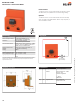
Dimensions (Inches [mm])
7.12 [181]
2.42 [61.6]
0.18 [4.6]
6.04 [153.4]
5.5 [140]
6.63 [168.5]
2 [50.8]
0.16 [4.1]
G/
OCC
W1
O/B
ECON-ZIP-BASE
ZIP Economizer™ Base Module
* The power consumption is for the control only and does not include connected loads
such as actuator, compressors, fans, and sensors. For transfomer sizing, the power
consumption of these attached components must be included.
** At low temperature the display has decreased response time. Below -22°F [-30°C] it will
not function.