
Install Instructions


7
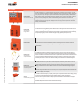
Tech.Doc - 03/21 - Subject to change. © Belimo Aircontrols (USA), Inc.
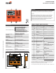
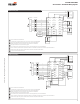
Differential Enthalpy
R
C
G/
OCC
W1/
O/B
Y1
Y2
ACT1 ACT2
ACT3
ACT5
R
C
R
C
G/OCC W1/O/B
Y1
Y2
CC1
CC2
OAT+
OAT-
OAH+
OAH-
SAT+
SAT-
RAT+
RAT-
RAH+
RAH-
-SR
1 -Common
2 + Hot
3 Y Input, 2 to 10V
5 U Output, 2 to 10V
ACT 1
ACT 2
ACT 3
ACT 5
R
C
Y1
Y2
ECON-ZIP-10K
Supply Air Temp
SAT +
SAT -
OAT +
OAT -
CC1
CC2
G/
OCC
W1/
O/B
RTU Stage 1
Mechanical Cooling
Circuitry
RTU Stage 2
Mechanical Cooling
Circuitry
ECON-ZIP-TH
Outside Air Enthalpy
ECON-ZIP-TH
Return Air Enthalpy
RAT+
T (+)
T (-)
24 V (R)
RH (+)
RH (-)
RAT-
RAH+
RAH-
R
T (+)
T (-)
24 V (R)
RH (+)
RH (-)
OAH +
OAH -
R
ECON-ZIP-BASE
THERMOSTAT RTU TERMINAL
57
50
52
51
53
50
56
58
59
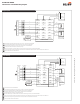
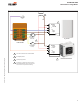
Differential Dry Bulb
R
C
G/
OCC
W1/
O/B
Y1
Y2
ACT1 ACT2
ACT3
ACT5
R
C
R
C
G/OCC
W1/O/B
Y1
Y2
CC1
CC2
OAT+
OAT-
OAH+
OAH-
SAT+
SAT-
RAT+
RAT-
RAH+
RAH-
-SR
1 -Common
2 + Hot
3 Y Input, 2 to 10V
5 U Output, 2 to 10V
ACT 1
ACT 2
ACT 3
ACT 5
R
C
Y1
Y2
ECON-ZIP-10K
Supply Air Temp
SAT +
SAT -
OAT +
OAT -
THERMOSTAT RTU TERMINAL
CC1
CC2
G/
OCC
W1/
O/B
RTU Stage 1
Mechanical Cooling
Circuitry
RTU Stage 2
Mechanical Cooling
Circuitry
ECON-ZIP-10K
Outside Air Temp
ECON-ZIP-10K
Return Air Temp
RAT+
ECON-ZIP-BASE
57
52
51
53
56
RAT-
58
59
Power source should be the same as ECON-ZIP-BASE.
50
When the thermostat is not equipped with occupancy control, "Fan On" output "G" shall be wired to the ECON-ZIP-BASE.
Existing refrigeration safety devices may exist, consult RTU wiring diagram
51
53
If RTU is not a Heat Pump using a conventional thermostat and it is desired to record heating operation hours, connect W1 to ECON-ZIP-BASE.
56
W1 must be wired for Heat Pump operation if conventional thermostat is used in conjunction with Defrost Board.
If Thermostat and RTU use O/B control reversing valve position, O/B must be wired to W1 on ECON-ZIP-BASE.
52
Actuators can be mounted in parallel with the ACT3 output from the ZIP Economizer. The ACT5 feedback input should be wired to the Outside Air damper actuator feedback wire.
57
Thermostat with two (2) stages of cooling required. Thermostats with mercury switches are not compatible with the ZIP Economizer.
58
Iso relay may be required with certain RTU manufacturers.
59
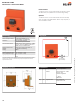
ECON-ZIP-BASE
ZIP Economizer™ Base Module Wiring Diagrams