SERVICE MANUAL (BSV-4251 BSV-4251A ) Service Manual MODEL NAME BSV-4251/4251A DOCUMENT NO RD(1) REVISION NO REVISION DATE 00 03/10/23 PAGE 1/75
SERVICE MANUAL (BSV-4251 BSV-4251A ) CONTENTS SPECIFICATION ..………………………………………………. 4 CONTROL DESCRIPTIONS …………………………………... 7 OPTIONS EXTRAS ..……………………..…………………… 9 REMOTE CONTROL BUTTONS ………..……………………. 10 DISPLAY CELL DEFECT SPECIFICATION …………………. 12 BLOCK & WIRING DIAGRAM …………………………………14 MODULE FUNCTION & DEFINITION ……………………….. 16 MODULE BASIC CONFIGURATION …………………….……17 VSC BOARD PIN CONFIGURATION …………….………….. 18 OSD MENU (FACTORY)……………………………………….. 21 DESCRIPTION OF VSC FUNCTIONS ………………………..
SERVICE MANUAL (BSV-4251 BSV-4251A ) (MODULE USE AND CONSIDERATIONS IN SERVICING) TROUBLESHOOTING.…….…………………………..…………. 53 IMAGE STICKING CHARACTERISTICS ……………………… 64 ISM MODE………………………………………………………….. 66 SCHEMATIC &PRINTED CIRCUIT BOARD &EXPLODE VIEW ……… 67 EXPLODED VIEW PARTS LIST ………………………………… 69 REPLACMENT PARTS LIST ……………………………………..
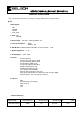
SERVICE MANUAL (BSV-4251 BSV-4251A ) SPECIFICATIONS Note : Specification and others are subject to change without notice for improvement. ● TV 1.Input Signal : PAL SECAM SD,HD VGA ~XGA 2. Tuner : PAL SECAM 2. Input Voltage : AC 100V ~ 240V,@ 50/60Hz, 4A 3. Power Consumption : 320W Stand-by : 5W 4. PDP Module : PDP42V51000,51300(YBT), 51330(new ASIC) - LGE 5. Speaker Impedance : 8 §Ù 6. Sound Output : 10W + 10W 7. Feature : - 8.
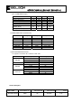
SERVICE MANUAL (BSV-4251 BSV-4251A ) 1) AV / COMPONENT Output ITEM AV Video Input Level AV Sync Input Level AV Burst Input Level AV Video Input Level AV Audio Input L/R Component Video Input Level (Y,Cb/Pb,Cr/Pr) Analog RGB, H/V Input Level MIN 0.85 0.24 0.14 0.47 0.47 TYP 1.00 0.29 0.28 0.63 0.63 MAX 1.15 0.32 0.35 0.79 0.79 UNIT Vpp Vpp Vpp V V 0.6 0.7 0.8 Vpp 0.6 0.7 0.
SERVICE MANUAL (BSV-4251 BSV-4251A ) Pin No Pin Name Spec Pin No Pin Name Spec 1 2 3 4 5 DCD RXD TXD DTR GND NC 12 Vpp 12 Vpp NC GND 6 7 8 9 DSR RTS CTS R NC NC NC NC CONTROL DESCRIPTIONS MODEL NAME BSV-4251/4251A DOCUMENT NO RD(1) REVISION NO 00 REVISION DATE 03/10/23 PAGE 6/75
SERVICE MANUAL (BSV-4251 BSV-4251A ) MODEL NAME BSV-4251/4251A DOCUMENT NO RD(1) REVISION NO 00 REVISION DATE 03/10/23 PAGE 7/75
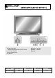
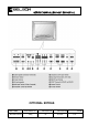
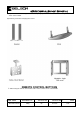
SERVICE MANUAL (BSV-4251 BSV-4251A ) OPTIONAL EXTRAS MODEL NAME BSV-4251/4251A DOCUMENT NO RD(1) REVISION NO 00 REVISION DATE 03/10/23 PAGE 8/75
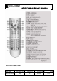
SERVICE MANUAL (BSV-4251 BSV-4251A ) ◐Optional extras can be changed or modified for quality improvement without notification new optional extras can be added. ◐Contract your dealer for buying these items. REMOTE CONTROL BUTTONS ※ When using the remote control aim it at the remote control sensor of the Monitor.
SERVICE MANUAL (BSV-4251 BSV-4251A ) TELETEXT FUNCTION MODEL NAME BSV-4251/4251A DOCUMENT NO RD(1) REVISION NO 00 REVISION DATE 03/10/23 PAGE 10/75
SERVICE MANUAL (BSV-4251 BSV-4251A ) DISPLAY CELL DEFECT SPECIFICATION MODEL NAME BSV-4251/4251A DOCUMENT NO RD(1) REVISION NO 00 REVISION DATE 03/10/23 PAGE 11/75
SERVICE MANUAL (BSV-4251 BSV-4251A ) [ PDP42V51000,51300,51330] DEFINITION OF CELL DEFECT ZONE MODEL NAME BSV-4251/4251A DOCUMENT NO RD(1) REVISION NO 00 REVISION DATE 03/10/23 PAGE 12/75
SERVICE MANUAL (BSV-4251 BSV-4251A ) 1) Definition of Cell defect Zone 2) Display Dot Diagram MODEL NAME BSV-4251/4251A DOCUMENT NO RD(1) REVISION NO 00 REVISION DATE 03/10/23 PAGE 13/75
SERVICE MANUAL (BSV-4251 BSV-4251A ) BSV-4251 &BSV-4251A (42") PDP TV BLOCK DIAGRAM 24LC21 EEPROM 3 Y,Pb,Pr COMPONENT1 (DTV) 80.000MHz 20.000MHz 5 R,G,B,H,V ANALOG RGB (U8) BA7657 SWITCH 5 TX0 + (U2) AD9883 A/D CONVERTER 24 24 CH1 RGB DE [23:0] 16 V OUT2 V SYNC CH1 GB (U39) VPC3230D-C5 VIDEO DECODER (SUB) 2 TUNER CVBS TX1 - H SYNC 3 Y,Pb,Pr TX1 + DO [23:0] 20.
SERVICE MANUAL (BSV-4251 BSV-4251A ) MODEL NAME BSV-4251/4251A DOCUMENT NO RD(1) REVISION NO 00 REVISION DATE 03/10/23 PAGE 15/75
SERVICE MANUAL (BSV-4251 BSV-4251A ) MODULE FUNCTION & DEFINITION 1.
SERVICE MANUAL (BSV-4251 BSV-4251A ) MODULE BASIC CONFIGURATION [PDP42V51000,51300,51330] MODEL NAME BSV-4251/4251A DOCUMENT NO RD(1) REVISION NO 00 REVISION DATE 03/10/23 PAGE 17/75
SERVICE MANUAL (BSV-4251 BSV-4251A ) VSC BOARD PIN CONFIGURATION J7 Pin No I/O Specification Description 1 ( 5V ) I 5V VSC 5V Input 2 ( 5V ) I 5V VSC 5V Input 3 ( 5V ) I 5V VSC 5V Input 4 ( GND ) GND 5V Ground 5 ( GND ) GND 5V Ground 6 ( GND ) GND 5V Ground 7 ( 12V ) I 12V VSC 12V Input 8 ( 12V ) I 12V VSC 12V Input 9 ( GND ) GND 12V Ground 10 ( GND ) GND 12V Ground 12V FAN 12V GND FAN 12V Ground AC POWER DETECT PORT 11 ( 12V ) I 12 ( GND ) : AC INPUT DETECTI
SERVICE MANUAL (BSV-4251 BSV-4251A ) J9 7 ( POWER ) I 5V / 0V LOCAL KEY INPUT PORT FOR POWER 8 ( VOL+ ) I 5V / 0V LOCAL KEY INPUT PORT FOR VOL + 9 ( VOL- ) I 5V / 0V LOCAL KEY INPUT PORT FOR VOL - 10 ( SRC/SEL ) I 5V / 0V LOCAL KEY INPUT PORT FOR SOURCE 11 (MENU) I 5V / 0V LOCAL KEY INPUT PORT FOR MENU 12 (CH-) I 5V / 0V LOCAL KEY INPUT PORT FOR CH- 13 (CH+) I 5V / 0V LOCAL KEY INPUT PORT FOR CH+ 1 ( 32V ) I 32V Audio AMP POWER INPUT PORT 2 ( 32V ) I 32V Audio AMP POWER
SERVICE MANUAL (BSV-4251 BSV-4251A ) 24 ( GND ) 0V 1 ( VCC5) I 5V 2 ( F_SC_L_IN ) I 0.5Vrms±3dB SCART1 AUDIO LEFT OUTPUT PORT 3 ( F_SC_R_IN ) I 0.5Vrms±3dB SCART1 AUDIO RIGHT OUTPUT PORT 4 ( GND ) 0V 5 ( H_ SC_L_IN ) I 0.5Vrms±3dB SCART2 AUDIO LEFT OUTPUT PORT 6 ( H_SC_R_IN ) I 0.5Vrms±3dB SCART2 AUDIO RIGHT OUTPUT PORT 7 ( GND ) 8 ( AFT ) 0V I 9 ( GND ) 10 ( TUNER_SIF ) 0V I 11 ( GND ) J2 5V INPUT 12 (TUNER_CVBS) 0V I TV VIDEO INPUT PORT 1.
SERVICE MANUAL (BSV-4251 BSV-4251A ) FACTORY MODE „ 1. Calibration : Automatic adjustment of white balance for Analogue input (PC) and Component2 (DTV) input. „ 2. Option Table 0002 : Initial installation of OSD. „ 3. Color control : Adjustment of contrast and brightness for scaler generating power. „ 4. PW565 : Adjustment of contrast and brightness for scaler input port (CH1 or CH2). „ 5. VPC3230-MAIN : Value adjustment for video decoder¡¯s brightness and contrast, color tickness in the main window. „ 6.
SERVICE MANUAL (BSV-4251 BSV-4251A ) CALIBRATION MENU „ 1. PC Calibration : Automatic adjustment as the fittest status of white balance for analogue input (PC) „ 2. DTV Calibration : Automatic adjustment as the fittest status of white balance for component2 (DTV) input.
SERVICE MANUAL (BSV-4251 BSV-4251A ) OPTION TABLE MENU „ Flesh tone „ LNA(Low Noise Amplifier) : On/Off Installation of screen quality improv ement fuc tion, when TV input signal is weak. „ Blue Screen : When there are no input signal of the TV and external equipment, you can install the screen color as blue. „ Melody Volume : Installation of the melody volume for initial soft power On/Off. The volume is exfactoried as ¡°0 ¡± due to license.
SERVICE MANUAL (BSV-4251 BSV-4251A ) COLOR CONTROL MENU „ Sub-Brightness : The brightness adjustment of scaler generating power. „ Red, Green, Blue Offset : The brightness adjustment of each Red, Green, Blue for scaler generating power. „ Brightness : The brightness adjustment of current screen. Adjustment value of brightness for User Menu „ TTX-Bright : It is not useful mode. „ Sub Contrast : Contrast adjustment of scaler generating power.
SERVICE MANUAL (BSV-4251 BSV-4251A ) PW565 MENU „ Red,Green,Blue Gain : The contrast value adjustment of each Red, Green, Blue for scaler input port (CH1 OR CH2) „ Red,Green,Blue Offset : The brightness adjustment of each Red, Green, Blue for scaler input port (CH1 OR CH2) „ APL „ Pixel Shift „ Pixel Number „ Time „ Virtual Framelock : Installation of flame frequency for panel (50Hz, 60Hz).
SERVICE MANUAL (BSV-4251 BSV-4251A ) VPC3230-MAIN MENU „ CT : Contrast adjustment of Composite & S-Video form¡¯s signal. „ BR : Brightness adjustment of Composite & S-Video form¡¯s signal. „ ACC_SAT „ TINT : The color sense adjustment of Composite & S-Video form¡¯s signal. „ SATCb : The blue color sense adjustment of Component & RGB form¡¯s signal. „ SATCr : The red color sense adjustment of Component & RGB form¡¯s signal „ CIPTNT : The color sense adjustment of Component & RGB form¡¯s signal.
SERVICE MANUAL (BSV-4251 BSV-4251A ) VPC3230-SUB MENU „ CT : The contrast adjustment of Composite & S-Video form¡¯s signal. „ BR : The brightness adjustment of Composite & S-Video form¡¯s signal. „ ACC_SAT „ TINT : The color sense adjustment of Composite & S-Video form¡¯s signal. „ SATCb : The blue color sense adjustment of Component & RGB form¡¯s signal. „ SATCr : The red color sense adjustment of Component & RGB form¡¯s signal. „ CIPTNT : The color sense adjustment of Component & RGB form¡¯s signal.
SERVICE MANUAL (BSV-4251 BSV-4251A ) ADC MENU „ Red, Green, Blue Gain : Control ADC input range (Contrast) of each respective channel. „ Red, Green, Blue Offset : Control dc offset (Brightness) of each respective channel. „ Current : Installation of PLL Part VCO Current. (For test) „ VCO : Installation of PLL Part VCO Range (For test) „ Pr, Y, Pb Gain : Contrast adjustment of Component2 Pr, Y, Pb signal. „ Pr, Y, Pb Offset : Brightness adjustment of Component2 Pr, Y, Pb signal.
SERVICE MANUAL (BSV-4251 BSV-4251A ) HEATRUN MENU „ 1. Auto Run : It is the mode to change the heatrun pattern as a certain time interval. „ 2. Luma Ramp (16 Step) : It is gray pattern of 16 Step. „ 3. Luma Ramp (128 Step) : It is gray pattern of 128 Step. „ 4. White 16 : It is low Gray pattern. „ 5. White 240 : It is high gray pattern. „ 6. Color Bar : It is color Bar Pattern. „ 7. RGB Ramp (32 Step) : It is RGB Ramp pattern of 32 Step.
SERVICE MANUAL (BSV-4251 BSV-4251A ) VERSION MENU „ Version : It is to show the Firmware Version. „ Release : It is to show the date of Firmware revision. „ Panel Used Time : It is to show the used time of Panel. „ Panel Name : It is to show the name of the PDP.
SERVICE MANUAL (BSV-4251 BSV-4251A ) SETUP MENU „ 1. TTX Language : Installation of initial language of the TTX. „ 2. Video : Video format per country and it is composed of Normal, NTSC, PAL N, M „ 3. Protocol : Installation of communication protocol for remote control. „ 4. LOGO : Installation to show company logo on the screen when power ¡°On¡±(ON/OFF).
SERVICE MANUAL (BSV-4251 BSV-4251A ) PSM (Picture Status Memory) Function to adjust picture status to an optimal condition in accordance with the type of program being viewed (standard, moving picture, movie, muted, game). SSM (Sound Status Memory) Function to adjust sound status to an optimal condition in accordance with the type of program being viewed (standard, music, movie, news). ARC (Aspect Ratio Control) Function to adjust the picture size. (16:9.
SERVICE MANUAL (BSV-4251 BSV-4251A ) EQUALIZER Function to control sound according to frequency. (100Hz, 300Hz, 1KHz, 3KHz, 10KHz) AVL (Auto Volume Leveler) Function to automatically adjust varying sound levels from each individual broadcasting company to an appropriate volume, in case of watching a television connected to external equipment. This allows to viewer to enjoy a comfortable and stable sound level even when changing the channel.
SERVICE MANUAL (BSV-4251 BSV-4251A ) Converts analog pictures (including Composite, S-Video, Component (480i) or the like) to Y-UV digital pictures. Compatible with various TV formats of NTSC, PAL, SECAM, etc. U41 (VPC323OD)_#28_S-LLC1 U42 (LM2937-3.3V)_#3_V3.3 LC18 (STS104B)_#2_VAA3230 MODEL NAME BSV-4251/4251A DOCUMENT NO RD(1) U40 (LM2937-3.3V)_#3_V3.
SERVICE MANUAL (BSV-4251 BSV-4251A ) LC16 (STS104B)_#2_VAA3230_1 U41 (VPC3230D)_#28_VID_CLK U41 (VPC3230D)_#53_INTLC U41 (VPC3230D)_#57_VID-VS U41 (VPC3230D)_#56_VID-HS MODEL NAME BSV-4251/4251A DOCUMENT NO RD(1) REVISION NO 00 REVISION DATE 03/10/23 PAGE 35/75
SERVICE MANUAL (BSV-4251 BSV-4251A ) AD9883 (A/D Converter) Converts an analog RGB signal to a process able digital signal. Converts a component signal (480p, 720p, 1080i) to a digital signal and transmits it to PW565 (Scaler).
SERVICE MANUAL (BSV-4251 BSV-4251A ) U1 (LM2937)_#3_ VO PW565 (Scaler) MODEL NAME BSV-4251/4251A DOCUMENT NO RD(1) REVISION NO 00 REVISION DATE 03/10/23 PAGE 37/75
SERVICE MANUAL (BSV-4251 BSV-4251A ) Receives, at the same time, a video signal from VPC3230, an Analog/Digital RGB signal and a Component signal, which are converted at AD9883 and THC63DV151, adjusted to a PDP display, and transmitted to a PDP module. In particular, it receives any PC signal input at various scanning rates and performs scaling to adjust to PDP resolution.
SERVICE MANUAL (BSV-4251 BSV-4251A ) Receives and converts any Sound IF signal from a TV Tuner to a general audio signal (LCD TV). Also, outputs the desired input signal out of many audio input signal options, and produces a woofer signal or Headphone signal as well as a general Speaker signal (LCD TV).
SERVICE MANUAL (BSV-4251 BSV-4251A ) LC20 (STS104B)_#2_C344_5VST LC21 (STS104B)_#2_C353_5VDD U15 (RC1117_3.
SERVICE MANUAL (BSV-4251 BSV-4251A ) MODULE SUPPLY VOLTAGE SEQUENCE [PDP42V5####] ¡Ü Life Expectancy The anticipated life-time is estimated more than 25,000 hours of continuous operations ¡Ø Average life time is the time when the brightness level becomes half of its initial value. MODEL NAME BSV-4251/4251A DOCUMENT NO RD(1) REVISION NO 00 .
SERVICE MANUAL (BSV-4251 BSV-4251A ) VSC POWER SEQUENCE Display Enable Relay On VaVs On 1. After Relay On • • • • 2. Continue 5Volt Monitoring – If there is no 5Volt more than 10 minutes, then power “Off” 3. Check if it is OK the 5Volt Mnt first. And then VaVs “On” after 3 seconds . 4. VaVs “On” --> waiting 3 seconds --> Display Enable “On”. 5. If 5Volt Mnt “Low” or AC-Det “Low”, immediately Display Enable “Off” and then VaVs “Off”, Relay “Off”.
SERVICE MANUAL (BSV-4251 BSV-4251A ) PSU POWER SEQUENCE [POWER DGK-420W] MODEL NAME BSV-4251/4251A DOCUMENT NO RD(1) REVISION NO 00 REVISION DATE 03/10/23 PAGE 43/75
SERVICE MANUAL (BSV-4251 BSV-4251A ) VOLTAGE & W/B ADJUSTMENT Power PCB Assy Voltage Adjustment 1-1-1. Va Adjustment (Address Voltage Adjustment) (°¡) Connect pin 9,10 of CN806 to(+) jack of D.M.M (³ª) After turning the VR2 (Va Adj),Voltage of D.M.M adjustment as same as Va voltage which on Label of panel right/bottom.(Deviation : ± 0.5V) 1-1-2. Vs Adjustment (°¡) Connect pin 1~3 of CN806 to (+) jack of D.M.M (³ª) After turning the VR3(Vs Adj),voltage of D.M.
SERVICE MANUAL (BSV-4251 BSV-4251A ) MODEL NAME BSV-4251/4251A DOCUMENT NO RD(1) REVISION NO 00 REVISION DATE 03/10/23 PAGE 45/75
SERVICE MANUAL (BSV-4251 BSV-4251A ) 2. W/B adjustment 2-2. Color temperature (White Balance) adjustment 1) How to enter Factory mode for adjustment of White Balance (1) PDP TV Power ¡°On¡± --> Input select key on Remote control. (2) Choose composite first and then PDP TV Power ¡°Off¡±. (3) PDP TV Power ¡°Off¡± and INFO on the R/C ==> ERASE ==> ENTER Key 2) For COMPOSITE adjustment (manual adjustment) (1) Signal Generator supply the pattern of above picture.
SERVICE MANUAL (BSV-4251 BSV-4251A ) (1) Signal Generator supply the pattern of above picture. Timing ¢¡ 395, Pattem ¢¡ 251, Reverse (720P, 60Hz) (2) After movement to 1.calibration on Factory Mode, move to sub menu as choice of volume button. (3) After movement to 2. DTV Calibration, choose it with volume button.
SERVICE MANUAL (BSV-4251 BSV-4251A ) (1) Signal Generator supply the pattern of above picture. Timing ¢¡ 313, Pattem ¢¡ 609 (1024 x 768, 60Hz) (2) After movement to 1.calibration on Factory Mode, move to sub menu as choice of volume button . (3) After movement to 2. PC Calibration, choose it with volume button.
SERVICE MANUAL (BSV-4251 BSV-4251A ) SAFETY PRECAUTIONS ( MODULE USE AND CONSIDERATIONS IN SERVICING) PDP Module is a display device to be divided into a Panel part and a Drive part. The Panel part consists of Electrodes, Phosphor, various dielectrics and gas, and the Drive part includes electronic circuitry and PCB. When using / handling this PDP Module, pay attention to the below warning and cautions.
SERVICE MANUAL (BSV-4251 BSV-4251A ) CAUTIONS (1) Do not place this product in a location that is subject to heavy vibration, or on an unstable surface such as an inclined surface. The product may fall off or fall over, causing injuries. (2) Before disconnecting cable from the product, be sure to turn off the power. Be sure to hold the connector when disconnecting cables.
SERVICE MANUAL (BSV-4251 BSV-4251A ) (15) If inserting high-power resistor(metal-oxide film resistor or metal film resistor) in order to repair, insert it as 10mm away as from a board. (16) During repairs, high voltage or high temperature components must be put away from a lead line. (17) This is a Cold Chassis but you had better use a cold transformer for safety during repairs. If repairing electricity source part, you must use the cold transformer.
SERVICE MANUAL (BSV-4251 BSV-4251A ) MODEL NAME BSV-4251/4251A DOCUMENT NO RD(1) REVISION NO 00 REVISION DATE 03/10/23 PAGE 52/75
SERVICE MANUAL (BSV-4251 BSV-4251A ) TROUBLE SHOOTING 1. Checking for no Picture A screen doesn if display at all and condition of black pattern or power off. (1) Check whether the CTRL B/D LED(D1~D4) is turned on or not. (2) Check the power and signal cable of CTRL B/D. (3) X B/D, Y B/D, Z B/D is well plugged in. (4) Check the connection of X B/D, Y B/D and Z B/D to CTRL B/D.
SERVICE MANUAL (BSV-4251 BSV-4251A ) ¡Ø Screen Display Form 2-2. The screen doesn’t be shown as Data COF (Include not be shown part of Data COF quantity or a part) (1) The problem between Data COF and X B/D is more possible that the screen is not be shown as data COF. (2) Confirm the connector of Data COF is well connected to X B/D.
SERVICE MANUAL (BSV-4251 BSV-4251A ) 2-3.
SERVICE MANUAL (BSV-4251 BSV-4251A ) 2-4. Regular Stripe is Generated about the Quantity of one Data COF IC or more (1) In case of generating regular stripe about the quantity of one Data COF IC, there is problem at the output of outputflatworm of X B/D In case of generating regular stripe about the quantity of two Data COF IC, that means the data which is conveyed from CTRL B/D doesn’t conveyed well. (2) Confirm the XB/D connection connector plugged in well. Correspond to unusual screen.
SERVICE MANUAL (BSV-4251 BSV-4251A ) Display X B/D Left Bottom of the Screen 4/7 Right X B/D Right Bottom of the Screen 3/7 Left X B/D ※ Screen Display Form 2-5. The screen display has a problem for Scan FFC. (1) It’s may be a problem between Scan FFC and Y B/D. (2) Check the connection of Y B/D and Scan COF. (3) If the Scan IC is failed, replace the Y DRV B/D. .
SERVICE MANUAL (BSV-4251 BSV-4251A ) 2-6. The screen has a vertical line with regular gap. (A vertical stripe flash at especial color) (1) This is a problem about control B/D. (2) Replace Control B/D. ※ Screen Display Form 2-7.
SERVICE MANUAL (BSV-4251 BSV-4251A ) (1) In this case, it’s due to incorrect marking of scan wave. (2) Replace a Y DRV B/D or Y SUS B/D. ※ Screen Display Form 2-8. The screen has one or several vertical line (1) In this case, It isn’t a problem about controller B/D or X B/D. (2) It may cause followings. - It’s out of order a panel - Open or short of DATA COF FPC attached panel - It’s out of order a DATA COF attached panel (3) Replace Module. 2- 9.
SERVICE MANUAL (BSV-4251 BSV-4251A ) (2) It may cause followings. - It’s out of order a panel - Open or short of SCAN FPC attached panel - It’s out of order a SCAN IC attached panel (3) Replace Y DRV B/D 2-10. The screen displays input signal pattern but the brightness is dark (1) In this case, Z B/D operation isn’t complete. (2) Check the power cord of Z B/D. (3) Check the connector of Z B/D and Controller B/D. (4) Replace the Controller B/D or Z B/D. 2-11.
SERVICE MANUAL (BSV-4251 BSV-4251A ) (3) Replace the Z B/D. 2-13. It doesn’t display a specified brightness at specified color (1) Check the connector of CTRL B/D input signal. (2) Replace the CTRL B/D. 3-1. No Power Nothing output of image.
SERVICE MANUAL (BSV-4251 BSV-4251A ) Check Input of AC (90V ~225V) Abnormal Connect plug with the set. Normal Check ST-BY LED ON Main S/W ON. Abnorma l Check AC Line Fuse Normal Abnormal Check LED YELL OW Sub S/W ON Check OPEN With CN806,CN13 Check the Vs Voltage IC1 5,IC16(PSU Part) and VSC Part Q30 Shor t Abnormal Replace IC15,IC16,Q30 Normal Check a connective condition and various connect or. 3-2. No Sound Check a connective condition of power cable Check voltage of sound terminal .
SERVICE MANUAL (BSV-4251 BSV-4251A ) Check AD9883 U2 Check BA7657 U8 Abnormal Input PC,DTV Signal Normal Abnorma l Check VPC3230 Dual U39,U41 Input DV D Signal Check PW565 RP12~18 Normal Abnormal Input Tuner-CVB S, CVBS,F/H SCART,S-Video Signal Abnormal Check CX A2089Q U3 Check SiI164 U48 Normal Check Cable Abnormal Input F/SCART RGB Signal Check BA7657 U28 3-4. No Sound Check co nnector Speaker t o set. Check CXA2089Q U3 Check MSP3450G U45 Check TDA7495S U14 Check Input Jack.
SERVICE MANUAL (BSV-4251 BSV-4251A ) In other words, the image sticking is defined as follows: when the same pattern(of the fixed display)is displayed for a long times, a difference in brightness is caused around the lighting area and non-lighting area due to deterioration in the fluorescent substance.
SERVICE MANUAL (BSV-4251 BSV-4251A ) order to minimize display period of the fixed pattern. Example of Proposal 4: During operation, the brightness of screen is suppressed as low as possible. For the display patterns, characters are indicated not on the black ground (non-picture area) but on the colored ground (mixture of R, G,B recommended).
SERVICE MANUAL (BSV-4251 BSV-4251A ) The basis of the evaluation was while the ISM Mode in the module was operating, the brightness decrease about 55 % of its initial value at the white window pattern ( 1/25 of full white pattern ) ISM operational conditions 1. Detective deviation : The change of APL Data is no less than ±4 and it will remain for more than 5 minutes. 2. Regardless of time, it will not operate where the display load is over 50%.
SERVICE MANUAL (BSV-4251 BSV-4251A ) ■ PSU(DGK-420W) BOTTOM MODEL NAME BSV-4251/4251A DOCUMENT NO RD(1) REVISION NO 00 REVISION DATE 03/10/23 PAGE 67/75
SERVICE MANUAL (BSV-4251 BSV-4251A ) EXPLODED VIEW PARTS LIST No Part no MODEL NAME BSV-4251/4251A Description DOCUMENT NO RD(1) REVISION NO 00 REVISION DATE 03/10/23 PAGE 68/75
SERVICE MANUAL (BSV-4251 BSV-4251A ) 2 S150110021 MAIN ASSY EPT-4200A(PAL) 3 S15012G021 FRONT FRAME ASSY EPT-4200A(PAL-STD) 4 S15013F016 FRAME FILTER ASSY EPM-4200A(MONITOR-STD) 5 S15014B016 FRAME ASSY EPM-4200B(MONITOR-STD) 2 S15012C021 JACK HOUSING ASSY EPT-4200(PAL) 4 S15014A021 FRONT ASSY EPT-4200A(PAL) 3 S15013C016 HEAT SINK ASSY EPM-4200A 3 S15013B016 MODULE ASSY EPM-4200A 2 S15012F016 AC IN-LET ASSY EPM-4200A 3 S150120036 VSC BOARD ASSY(TOP) EPT-4200AP 2 S150113036 VSC
SERVICE MANUAL (BSV-4251 BSV-4251A ) 4 71AELP125 BRKT PW EGI 1T 4 73DELi032 INSULATION SW PC 0.
SERVICE MANUAL (BSV-4251 BSV-4251A ) No Part no Description IC 4 01-0019 4 01-0020 IC REG LM317EMP SOT-223 4 01-0059 IC REG RC1117S33 SOT-223 4 01-0071 IC REG KIA7809AF D-PAK 4 01-0088 IC REG KIA7805AF D-PAK 4 01-0089 IC REG KIA7808AF D-PAK 4 01-0273 IC REG NCP1117ST18T30 4 01-0040 IC EEPROM 24LC16B SOP-08 4 01-0041 IC EEPROM 24LC21A SOP-08 4 01-0053 01-0055 01-0057 01-0225 01-0091 01-0073 01-0108 01-0253 01-0259 01-0260 01-0261 01-0262 01-0263 01-0264 01-0265 01-0266 01-0278 0
SERVICE MANUAL (BSV-4251 BSV-4251A ) 4 5 4 3 7 4 04-0128 04-0127 04-0128 04-0038 04-0033 04-0053 DIODE KDZ8.2EV-RTK DIODE 1SR154-400 DIODE KDZ8.
SERVICE MANUAL (BSV-4251 BSV-4251A ) 4 4 4 3 7 3 3 3 3 3 4 11-0045 11-0048 11-0049 11-0054 11-0042 11-0010 11-0054 11-0148 12-0003 12-0004 13-0002 EC SMD MV 16V 10UF (4X5.3) TP EC SMD MV 16V 100UF (6.3X5.3) TP EC SMD MV 16V 47UF (6.3X5.3) TP EC SHL 50V 470UF (10X20) EC SRA 16V 47UF (6.3X7) EC SHL 16V 470UF (8X11.5) EC SHL 50V 470UF (10X20) EC KMG 50V 1000UF (12.5X25) PC PE 50V 104J RST PC 10PS 470MJ 12 (10X12.
SERVICE MANUAL (BSV-4251 BSV-4251A ) 5 5 5 5 5 5 5 5 5 5 5 5 5 5 5 5 5 5 5 5 5 4 4 4 4 4 4 3 14-0030 14-0034 14-0037 14-0043 14-0045 14-0050 14-0052 14-0055 14-0064 14-0066 14-0069 14-0107 14-0128 14-0175 14-0178 14-0179 14-0205 14-0268 14-0270 14-0321 14-0476 14-0008 14-0010 14-0012 14-0052 14-0055 14-0069 14-0181 R CHIP 1608 202F TP R CHIP 1608 223F TP R CHIP 1608 271J TP R CHIP 1608 332F TP R CHIP 1608 333J TP R CHIP 1608 470F TP R CHIP 1608 472F TP R CHIP 1608 473J TP R CHIP 1608 562J TP R CHIP 1608 6
SERVICE MANUAL (BSV-4251 BSV-4251A ) EXPLODE VIEW MODEL NAME BSV-4251/4251A DOCUMENT NO RD(1) REVISION NO 00 REVISION DATE 03/10/23 PAGE 75/75