
Owner`s manual

Page 5
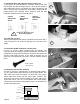
10. Adjust the miter gauge track to fit your miter gauge.
Begin this step by first test fitting your miter gauge for fit. If it fits
too tightly, lightly squeeze the gib towards the front edge of the
track to open it wider. Protect the edges with a cloth. Next,
install the (12) 1/4-28 x 1/2" set screws into the track. The screws
tighten the miter track by deflecting the gib. Tighten all the
screws uniformly and gradually until desired fit is achieved. Use
the supplied 1/8" Allen wrench. The slot is designed to fit your
standard 3/4 x 3/8" miter gauge bars. Use the "t" slot to mount
accessories. (It's the smaller slot, and accepts 1/4" hex bolts).
Wax the track and bar to prevent undue wear!
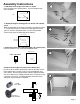
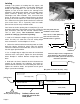
12. Attach the nylon door handle.
Use the (2) #8 x 1-1/8" screws, as shown.
Note: you may have extra set screws.
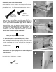
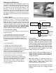
9. Attach the miter track to the routertop.
First install (2) 1/4" cross dowels in the cabinet side panels. The
center miter track screw attaches to a factory installed insert.
Use the (2) 1/4-20 x 2" phil. flat head machine screws in the
outside track holes. The center track hole uses the 1/4-20 x 1"
phil. flat head machine screw.
1/4-20 x 2"
phil. flat head
machine screw
1/4-20 x 1"
phil. flat head
machine screw
#8 x1-1/8"
screw
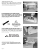
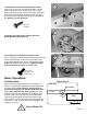
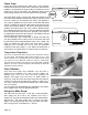
11. Adjust the leveling screws until the insert is flush.
First, remove the protective paper from your acrylic router insert
plate, and drop it into the routertop opening. Here, the user is
checking flushness with his right hand while adjusting the
leveling screws with his left. Fine adjust the six screws at the
four corners of the insert opening first. Then, adjust the
remaining screws.
Important! In step 18 you will mount your router to the insert
plate. After that, you may again need to fine adjust the
plate's flushness.
I
I
10
9
11
12