RDR 2100 PG Cover 3/12/07 3:43 PM Page 1 RDR 2100 Pilot’s Guide Digital Weather Radar System B 006-18002-0000 Revision 1 N
RDR 2100 PG Cover 3/12/07 3:43 PM Page 2 WARNING Information subject to the export control laws. This document, which includes any attachments and exhibits hereto, contains information subject to International Traffic in Arms Regulation (ITAR) or Export Administration Regulation (EAR) of 1979, which may not be exported, released or disclosed to foreign nationals inside or outside the U.S. without first obtaining an export license.
RDR 2100 toc 3/12/07 3:46 PM Page i Table of Contents RDR 2100 OPERATIONAL CONTROLS . . . . . . . . . . . . . . . . . . . . . . . . . . . .1 TEST PATTERN . . . . . . . . . . . . . . . . . . . . . . . . . . . . . . . . . . . . . . . . . . . .4 FAULT ANNUNCIATIONS . . . . . . . . . . . . . . . . . . . . . . . . . . . . . . . . . . . . .4 PREFLIGHT . . . . . . . . . . . . . . . . . . . . . . . . . . . . . . . . . . . . . . . . . . . . . . . . . . .5 PREFLIGHT WARNINGS . . . . . . . . . . . . . . . . . . .
RDR 2100 toc 3/12/07 3:46 PM Page ii Table of Contents TARGET RESOLUTION . . . . . . . . . . . . . . . . . . . . . . . . . . . . . . . . .31 RANGE RESOLUTION . . . . . . . . . . . . . . . . . . . . . . . . . . . . . . . . . .31 AZIMUTH RESOLUTION . . . . . . . . . . . . . . . . . . . . . . . . . . . . . . . . .32 PATH PLANNING . . . . . . . . . . . . . . . . . . . . . . . . . . . . . . . . . . . . . . . . . .32 PATH PLANNING CONSIDERATIONS . . . . . . . . . . . . . . . . . . . . .
RDR 2100 PG 3/12/07 3:44 PM Page 1 Operational Controls RDR 2100 OPERATIONAL CONTROLS BRT - Controls brightness of the indicator display (CW rotation for max brightness). Wx/WxA - Alternately selects between the Wx (weather) and WxA (weather-alert) modes of operation. “Wx” or “WxA” will appear in the lower left of the display. Wx or WxA colors are: Black for no returns, Green for weak returns, Yellow for moderate returns, Red for heavy returns and Magenta for intense returns.
RDR 2100 PG 3/12/07 3:44 PM Page 2 Operational Controls GAIN - The gain knob adjusts the radar gain from 0 to -20 dB (CCW rotation reduces gain). The gain knob will only function when in the MAP mode. PULL ARL - (Automatic Range Limiting) - Displays a blue area behind weather systems where weather detection is no longer possible because of attenuation. LOG - Used when Bendix/King radar graphics units are installed. A listing of the latitudes and longitudes of selected waypoints are displayed.
RDR 2100 PG 3/12/07 3:44 PM Page 3 Operational Controls OFF - Removes primary power from the radar indicator, but the radar still has power applied. The radar will remain active with no radar transmissions occurring, for up to a maximum time of 30 seconds. This time delay allows time to park the antenna at 0 degrees azimuth and 30 degrees tilt down. Note: The only way to remove primary power from the radar is to pull the radar circuit breaker.
RDR 2100 PG 3/12/07 3:44 PM Page 4 Operational Controls TEST PATTERN FAULT ANNUNCIATIONS Fault annunciations are a method of alerting the pilot that the radar system is not performing to established standards. Built-in test equipment (BITE) automatically and constantly tests the radar system. If a fault occurs, the fault annunciation will be presented on the Display unit. There are two general categories of faults: hard failures and soft failure/annunciations.
RDR 2100 PG 3/12/07 3:44 PM Page 5 Preflight Note: A TX FLT is indicated if the Strut switch is configured to be active and the aircraft is on the ground. Soft failures are those which can cause limited system operation, Radar data will still be displayed but the flight crew should be aware that the display does not necessarily represent the true weather. Soft failures are typically configuration problem, stabilization problems, or some similar problem.
RDR 2100 PG 3/12/07 3:44 PM Page 6 Preflight 2) With the function switch in TST or SBY, taxi to a clear area where there are no people, aircraft, vehicles, or metallic buildings within approximately 100 yards. 3) Rotate the function switch to ON. The indicator will automatically display in the Wx mode and 80 nm range. Any targets (weather or ground) will be displayed in green, yellow, red, or magenta. (Note: A 60 second warm up time period is required before the system will transmit).
RDR 2100 PG 3/12/07 3:44 PM Page 7 Theory of Operation THEORY OF OPERATION GENERAL The primary use of this radar is to aid the pilot in avoiding thunderstorms and associated turbulence. Since each operator normally develops specific operational procedures for use of weather avoidance radar, the following information is presented for use at the operator’s discretion. Operational techniques for the RDR 2100 are similar to earlier generation weather avoidance radars.
RDR 2100 PG 3/12/07 3:44 PM Page 8 Theory of Operation WEATHER RADAR PRINCIPLES Airborne weather avoidance radar, as its name implies, is for avoiding severe weather, not for penetrating it. Whether to fly into an area of radar echoes depends on echo-intensity, spacing between the echoes, aircraft capabilities and pilot experience. Remember that weather radar detects only precipitation drops; it does not detect minute cloud droplets, nor does it detect turbulence.
RDR 2100 PG 3/12/07 3:44 PM Page 9 Theory of Operation Note that the antenna gain versus angle characteristic is a continuous function at all angles. This means that there is a gain value associated with all forward angles relative to the selected tilt angle. In this figure the tilt angle is shown as zero degrees. This means the beam center is along the same angle as the aircraft flight angle.
RDR 2100 PG 3/12/07 3:45 PM Page 10 Theory of Operation In this scenario the weather cell might be at 100 nm, the altitude might be 40,000 feet, and the appropriate tilt angle is approximately -3 degrees. Notice that the beam is centered on the rain but it also intersects the ground. The angle the beam makes with the ground is called the grazing angle. When this angle gets greater than about 2 degrees the ground reflections that return to the radar become very significant.
RDR 2100 PG 3/12/07 3:45 PM Page 11 Theory of Operation RADAR REFLECTIVITY What target will reflect the radar’s pulses and thus be displayed on the indicator? Only precipitation (or objects more dense than water such as earth or solid structures) will be detected by an X-band weather radar. Therefore weather radar does not detect clouds, thunderstorms or turbulence directly. Instead, it detects precipitation which may be associated with dangerous thunderstorms and turbulence.
RDR 2100 PG 3/12/07 3:45 PM Page 12 Theory of Operation WEATHER DISPLAY CALIBRATION The radar display has been calibrated to show five levels of target intensity: Black (level 0), Green (level 1), Yellow (level 2), Red (level 3), and Magenta (level 4). The meaning of these levels is shown in the following chart as to their approximate relationship to the Video Integration Processor (VIP) intensity levels used by the National Weather Service.
RDR 2100 PG 3/12/07 3:45 PM Page 13 Theory of Operation WEATHER ATTENUATION COMPENSATION An extremely important phenomena for the weather avoidance radar operator to understand is that of attenuation. When a radar pulse is transmitted into the atmosphere, it is progressively absorbed and scattered so that it loses its ability to return to the antenna. This attenuation or weakening of the radar pulse is caused by two primary sources, distance and precipitation.
RDR 2100 PG 3/12/07 3:45 PM Page 14 Theory of Operation Attenuation can also be a problem when flying in a large area of general rain. If the rain is moderate, the radar beam may only reach 20 or 30 miles before it is fully attenuated. The pilot may fly along for many miles seeing the same 20-30 nautical miles of precipitation ahead on the radar when, actually, the rain may extend a great distance.
RDR 2100 PG 3/12/07 3:45 PM Page 15 Theory of Operation AUTOMATIC RANGE LIMITING (ARL) The RDR 2100 contains Automatic Range Limiting (ARL) circuitry which causes the display to depict areas that the radar cannot penetrate due to signal attenuation. Typically, the ARL display will show blue areas on the far side of a series of severe weather systems. This cautions the pilot to avoid flight into the blue areas due to the uncertainty of weather conditions.
RDR 2100 PG 3/12/07 3:45 PM Page 16 Theory of Operation TARGET ALERT The RDR 2100 system can be configured at installation to include the Target Alert feature. The purpose of the feature is to alert the pilot to the presence of a significant weather cell that exists beyond the currently selected range. For this mode to be active, Wx or WxA mode must be selected and Vertical Profile must not be selected.
RDR 2100 PG 3/12/07 3:45 PM Page 17 Theory of Operation ALTITUDE RING (RANGE RING) Not all radar transmitted energy is contained in the main beam radiation pattern. Some of the energy is radiated in the side lobe pattern. The characteristics of some radomes and/or nose caps can cause detrimental side lobe radiation. Should this occur, the side lobe can be radiated down toward the earth and the reflected energy received by the radar may be displayed on the indicator as a narrow ring of video.
RDR 2100 PG 3/12/07 3:45 PM Page 18 Theory of Operation RADOMES A radome is a covering that shields the radar antenna from hostile environments, such as fast moving air, rain, bugs, and ice. It allows the microwave energy to pass through relatively undisturbed. This means that very little of the microwave energy passing through it will be absorbed, reflected, or redirected as a result of it’s presence. Some radomes closely approximate this definition, while others do not.
RDR 2100 PG 3/12/07 3:45 PM Page 19 Weather Mapping and Interpretation WEATHER MAPPING AND INTERPRETATION This section contains general information on use of radar for weather interpretation. Review of this information will assist the operator in using radar. Note: The ability of a weather radar system to display weather returns is dependent upon the radome Transmission Efficiency. Bendix/King recommends a 90% average/85% minimum transmission efficiency.
RDR 2100 PG 3/12/07 3:45 PM Page 20 Weather Mapping and Interpretation THUNDERSTORMS & TURBULENCE The RDR 2100 can give you a clue to the presence of turbulence. Areas of the display where the colors change rapidly over a short distance represent steep rainfall gradients, which are usually associated with severe turbulence. Turbulence may be divided into two basic types: (1) clear-air turbulence; and (2) turbulence associated with thunderstorms and precipitation. The latter is most common.
RDR 2100 PG 3/12/07 3:45 PM Page 21 Weather Mapping and Interpretation not be much more than a blunt projection or a scalloped edge of the parent thunderstorm echo. A crescent-shaped indentation on the side of a major thunderstorm echo 3 to 7 miles long is another possible identifier of an active or potential tornado in the vicinity. The best procedure is to make wider than usual detours around sharpedged thunderstorms and especially those which show projections or crescent-shaped indentations.
RDR 2100 PG 3/12/07 3:45 PM Page 22 Weather Mapping and Interpretation These echoes appear quite suddenly and along any edge of the storm outline. They also change in intensity and shape in a matter of seconds, and for this reason careful monitoring of the display is essential. It must be noted that weak or fuzzy projections are not normally associated with hail; however, such echoes should be watched closely for signs of rapid intensification.
RDR 2100 PG 3/12/07 3:45 PM Page 23 Ground Mapping and Interpretation LIGHTNING AND STATIC DISCHARGES Lightning and static discharges could scatter the display momentarily. However, the general presentation is unaffected and should return to normal within 1 scan. Above all, remember: Never regard any thunderstorm as LIGHT, even when radar observers report the echoes are of light intensity. Avoiding thunderstorms is the best policy.
RDR 2100 PG 3/12/07 3:45 PM Page 24 Ground Mapping and Interpretation GROUND MAPPING AND INTERPRETATION A secondary objective of the radar system is gathering and presentation of terrain data. This data is represented in the form of a topographical map that can be employed as a supplement to standard navigation procedures. Target quality affects the indicator display in various situations.
RDR 2100 PG 3/12/07 3:45 PM Page 25 Ground Mapping and Interpretation LOOKING ANGLE The incident angle at which the terrain is illuminated has a direct bearing on the detectable range and the area of illumination. A large incident angle gives the radar system a smaller detectable range of operation (due to a minimized reflection of direct radar energy). However, the illuminated area “A” is larger.
RDR 2100 PG 3/12/07 3:45 PM Page 26 Operation In-Flight OPERATION IN-FLIGHT GENERAL The RDR 2100 will provide you with target information to a greater degree of clarity than has ever been possible with previous generation weather avoidance radars. It is the purpose of this section to help you become a proficient radar operator as soon as possible. However, it is realized that proficiency can only improve with usage.
RDR 2100 PG 3/12/07 3:45 PM Page 27 Operation In-Flight In practice, when flying over fairly even terrain, ground returns are difficult to paint when the angle of incidence of the radiated beam becomes large (see Looking Angle pg. 25) and, therefore, causes the beam to travel almost parallel to the ground (see figure below.) However, objects such as large buildings in cities, steep hills, mountains or storms will reflect the signal and can show strong returns at distances greater than those shown below.
RDR 2100 PG 3/12/07 3:45 PM Page 28 Operation In-Flight forest). EARLY DETECTION OF ENROUTE WEATHER To set the antenna tilt to optimize the radar’s ability to quickly identify significant weather, follow these steps: 1) Select the Wx (weather) mode of operation. Adjust Brightness control as desired. 2) Select the 40 or 80 nm range. 3) Adjust the antenna tilt control down until the entire display is filled with ground returns.
RDR 2100 PG 3/12/07 3:45 PM Page 29 Operation In-Flight Significant weather will show a stronger return than ground return at shallow angles. A weather target will show as a solid mass while mountains will show a gap behind the peaks. Raise tilt until a weather target emerges from the ground returns.
RDR 2100 PG 3/12/07 3:45 PM Page 30 Operation In-Flight Raise tilt angle until weather is separated from the ground. Note that displayed range of the ground target will increase as tilt angle is increased.
RDR 2100 PG 3/12/07 3:45 PM Page 31 Operation In-Flight SHADOWED AREAS Extremely heavy rainfall can reduce the ability of the radar energy to penetrate a weather cell and present a complete picture of the weather area. This condition is referred to as “radar attenuation”. Under these conditions ground returns can be helpful in analyzing the weather situation. Tilt the antenna down and observe the ground returns around the displayed cell.
RDR 2100 PG 3/12/07 3:45 PM Page 32 Operation In-Flight AZIMUTH RESOLUTION The ability of the radar to resolve adjacent targets in azimuth is a function of the beam width of the antenna and the range to the target. As can be seen in the adjacent table, the diameter of this radiated beam increases as it gets further away from the aircraft. Targets separated by a distance less than the beam diameter (at the target distance) will merge and appear on the indicator as “one.
RDR 2100 PG 3/12/07 3:45 PM Page 33 Operation In-Flight PATH PLANNING CONSIDERATIONS • Avoid cells containing magenta and red areas by at least 20 nautical miles. • Do not deviate downwind unless absolute necessary. Your chances of encountering severe turbulence and damaging hail are greatly reduced by selecting the upwind side of the storm.
RDR 2100 PG 3/12/07 3:45 PM Page 34 Operation In-Flight A “Blind Alley” or “Box Canyon” situation can be very dangerous when viewing the short ranges. Periodically switch to longer-range displays to observe distant conditions. As shown below, the short-range returns show an obvious corridor between two areas of heavy rainfall but the long-range setting shows a larger area of heavy rainfall.
RDR 2100 PG 3/12/07 3:45 PM Page 35 Antenna Stabilization ANTENNA STABILIZATION CRITERIA Automatic antenna stabilization, as employed in today’s weather avoidance radar, consists of an electro-mechanical means of maintaining a selected beam scan relative to the earth’s horizon during moderate aircraft maneuvers. To accomplish this, a reference is established by the aircraft’s vertical gyro, usually a component of the auto pilot or integrated flight control system.
RDR 2100 PG 3/12/07 3:45 PM Page 36 Antenna Stabilization EFFECT ON RADAR STABILIZATION Previously discussed gyro precession errors will directly affect radar stabilization, and therefore the quality of return seen on the indicator. Radar on aircraft flying at high altitude is normally operated on the 80 to 240 nm range with the antenna tilted down slightly so the radar beam is just above the point of painting ground returns.
RDR 2100 PG 3/12/07 3:45 PM Page 37 Antenna Stabilization DURING TAKEOFF Since there is no advantage in having the antenna tilt level while at low altitudes, raising the antenna tilt to clear ground returns caused by gyro acceleration error will result in satisfactory radar operation. Tilt can then be readjusted as the vertical gyro stabilizes. Turns during climb-out, while pitch acceleration error exists, will also cause a stabilization error in the roll axis.
RDR 2100 PG 3/12/07 3:45 PM Page 38 Antenna Stabilization introduce a three to five degree antenna stabilization error which may persist as long as 5 minutes after the maneuver. Precession error results in a “lopsided” antenna scan; low on one side, high on the other. If the picture is extremely “dirty” in the forward area-antenna looking at terrain rather than precipitation-use a slight degree of up tilt. In the azimuth scan area near 45° left or right, the beam tilt is close to that indicated.
RDR 2100 PG 3/12/07 3:45 PM Page 39 Antenna Stabilization Stabilization of the radar beam compensates for moderate aircraft maneuvers. The Line-of-Sight system used is not absolute, but has limitations. Recognize limitation errors. Errors in the order of one-half degree or less can produce this effect. With the beam just contacting the horizon at 180 nautical miles, a 1/2 degree of further down tilt moves this contact point in to 130 nautical miles. Isolated terrain targets would now appear.
RDR 2100 PG 3/12/07 3:45 PM Page 40 Antenna Stabilization 6. Turn the STAB on. If the pattern appears as Figure 2 or 3, the RDR 2100 can compensate for this using ROLL TRIM. Adjust the ROLL TRIM with a small screwdriver through access on radar indicator controller until figure 1 is achieved. 7. Roll the aircraft gently to the right auto pilot bank angle. 8. For perfect stabilization, the pattern shown in Figure 1 should not shift.
RDR 2100 PG 3/12/07 3:45 PM Page 41 VP Operation In-Flight VERTICAL PROFILE (VP) THEORY OF OPERATION The primary use of the RDR 2100 is to aid the pilot in avoiding thunderstorms and associated turbulence. All normal weather radar principals apply to the Vertical Profile feature incorporated in the RDR 2100 radar.
RDR 2100 PG 3/12/07 3:45 PM Page 42 VP Operation In-Flight OPERATION Whether you are a highly experienced weather avoidance radar operator or are using radar for the first time, you will find operating the Vertical Profile feature easy. In fact, most will find that Vertical Profile simplifies normal operation. The best time to begin using Vertical Profile is on a nice sunny day when the pilot work load will allow time to experiment with the new feature.
RDR 2100 PG 3/12/07 3:45 PM Page 43 VP Operation In-Flight Lateral clearance of at least 20 nautical miles is recommended for all storm cells providing red or magenta level returns. Note: The NAV MAP mode is disabled during Vertical Profile operation. A few seconds will normally elapse before the display will paint the Vertical Profile radar returns. This delay is due to the time it takes the antenna to move to the selected azimuth position to begin the vertical scan pattern.
RDR 2100 PG 3/12/07 3:45 PM Page 44 VP Operation In-Flight Center of Ground Return Figure 5: Vertical Profile View Ground Returns Aircraft at 20,000 feet MSL Figure 5A: Standard Azimuth View Aircraft at 20,000 feet MSL Figure 5: 40 nm range selected showing normal ground returns over that terrain. The aircraft is at 20,000 feet MSL. The flashlight like beam image provides a good representation of the radar beam characteristics. The center line of this image is the ground.
RDR 2100 PG 3/12/07 3:45 PM Page 45 VP Operation In-Flight Center of Ground Return “Symmetrical” Image on Both Sides of Beam - see note below Figure 6: Vertical Profile View Ground Mapping Denver & Mountains Aircraft at 20,000 feet MSL Figure 6A: Standard Azimuth View Ground Mapping Denver & Mountains Aircraft at 20,000 feet MSL Figure 6: 160 nm range selected showing normal ground returns over flat terrain with Denver and the background mountains displayed as strong symmetrical ground returns at 130
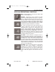
RDR 2100 PG 3/12/07 3:45 PM Page 46 VP Operation In-Flight NonSymmetrical Return Indicates Weather Center of Ground Return Figure 7: Vertical Profile View Isolated Low Level Weather Aircraft at 20,000 feet MSL Figure 7A Standard Azimuth View Isolated Low Level Weather Aircraft at 20,000 feet MSL Figure 7: 80 nm range selected showing normal ground returns over flat terrain. An isolated low level storm at 50 nautical miles is depicted by the non-symmetrical return. The aircraft is at 20,000 feet MSL.
RDR 2100 PG 3/12/07 3:45 PM Page 47 VP Operation In-Flight NonSymmetrical Return Indicates Weather Center of Ground Return Figure 8 Vertical Profile View Strong Weather Line Aircraft at 20,000 feet MSL Figure 8A Standard Azimuth View Strong Weather Line Aircraft at 20,000 feet MSL Figure 8: 80 nm range selected showing normal ground returns out to 60 nautical miles. An intense high-level storm is depicted by the nonsymmetrical returns. The aircraft is at 20,000 feet MSL.
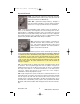
RDR 2100 PG 3/12/07 3:45 PM Page 48 VP Operation In-Flight NonSymmetrical Return Indicates Weather Center of Ground Return Figure 9: Vertical Profile View Strong Weather Returns Aircraft at 20,000 feet MSL Figure 9A: Standard Azimuth View Strong Weather Returns Aircraft at 20,000 feet MSL Figure 9: 40 nm range selected showing normal ground returns out to 25 nautical miles.
RDR 2100 PG 3/12/07 3:45 PM Page 49 VP Operation In-Flight NonSymmetrical Return Indicates Weather +30° Scan Up Limit Storm Extends Past the Point Center of Ground Return “Symmetrical” Ground Returns - see note below Possible Weather Returns Figure 10: Vertical Profile View Low Level Weather & Ground Returns Aircraft on Ground at Fort Collins Loveland, Colorado Figure 10A: Standard Azimuth View Low Level Weather Ground Returns Aircraft on Ground in Fort Collins Loveland Colorado Note: The image wil
RDR 2100 PG 3/12/07 3:45 PM Page 50 VP Operation In-Flight interesting point to note between the azimuth and VP presentation is the storm depth painted. The Vertical Profile presentation depicts the storm tops to be 7 nautical miles deep while the azimuth view depicts a storm depth of 2 nautical miles. The selected tilt angle would account for this discrepancy. The vertical scan in the Vertical Profile mode of operation is up and down 30 degrees.
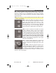
RDR 2100 PG 3/12/07 3:45 PM Page 51 Weather Radar Interference WEATHER RADAR INTERFERENCE There are at least four common types of external interference that may cause spokes to appear on the radar display. The first type of interference is referred to as CW (Continuous Wave). Figures 11 through 14 show variations of this type of interference. One possible source is ground based microwave data links. Another source is various kinds of military equipment.
RDR 2100 PG 3/12/07 3:45 PM Page 52 Weather Radar Interference at different azimuth angles (see Figures 13 and 14). This phenomenon results from the side-beam characteristics of the antenna. If the source of interference is an airborne jammer, multiple spokes may be displayed as in Figures 11 and 13. Normally, adjusting the antenna tilt angle to extreme up or down angles will reduce, or even eliminate, this type of interference.
RDR 2100 PG 3/12/07 3:45 PM Page 53 Weather Radar Interference The third common source of interference occurs when another weather radar system with similar characteristics is transmitting in the area. Figure 16 shows what is displayed in this situation. These are commonly referred to as “rabbit tracks”.
RDR 2100 PG 3/12/07 3:45 PM Page 54 Options OPTIONS CHECKLIST With an optional checklist unit installed, the pilot is provided with up to 935 lines of programmable information. These pages may be custom programmed by the pilot for the specific aircraft’s performance specifications. When the checklist is switched ON, the radar screen will display checklists. Note that the radar does not transmit when the checklist is displayed. Selecting the checklist overrides all other indicator displays.
RDR 2100 PG 3/12/07 3:45 PM Page 55 Options MOVING-MAP NAVIGATION When your radar is equipped with the proper Bendix/King radar graphics unit (IU-2023B, GC-360A, GC-381A) with a Bendix/King Flight Management System (KNS-660, KNS-81, KLN-88, KLN-90/B, KLN 900, GNS-XLS) or NAV System (KNR 634A, KDM 706A or DM 441B), it is possible to display one or more way points as well as the flight path to the way points. Refer to the pilot’s manuals on these units for details of their operation.
RDR 2100 PG 3/12/07 3:45 PM Page 56 Options B ELECTRONIC FLIGHT INSTRUMENTATION SYSTEM (EFIS) When the RDR 2100 is integrated into a Bendix/King EFIS the following options are available: SPLIT SCREEN Split Screen allows weather to be tracked in both traditional and vertical profile modes on the screen at the same time.
RDR 2100 PG 3/12/07 3:45 PM Page 57 Options LOG SCALE Log Scale allows viewing of a close storm in great detail while simultaneously viewing a smaller-scale depiction of distant weather.
RDR 2100 PG 3/12/07 3:45 PM Page 58 Options 60°° SECTOR SCAN 60° Sector Scan allows faster updates on rapidly changing areas by isolating a 60 degree sector. Note: Sector Scan is only available on certain radar control panel versions.
RDR 2100 PG 3/12/07 3:45 PM Page 59 Options AUTO STEP SCAN Auto Step Scan causes the antenna tilt to sequentially step in 4° increments. This allows the pilot to Vertical Profile the entire azimuth scan angle by simply watching successive antenna scans. Auto Step Scan is entered by turning the tilt adjust to +15° or -15°. If the tilt angle is set to -15°, the following is the sequence of antenna tilt angles for each azimuth scan: -10°, -6°, -2°, +2°, +6°, +10° ....+6°, +2°, etc.
RDR 2100 PG 3/12/07 3:45 PM Page 60 Specifications SPECIFICATIONS RDR 2100 SENSOR (ANTENNA, RECEIVER, TRANSMITTER) Performance Index - 10 inch 213.9 ±2.5 dB - 12 inch 216.7 ±2.5 dB - 18 inch 225.3 ±2.5 dB Displayed Weather Ranges 5, 10, 20, 40, 80,160, 240, 320 nm Weather Colors 5 Including Black Vertical Profile ± 30° Ground Map Variable Gain 0 to -20 dB (configurable at installation) Attenuation Compensation 3 to 320 nm Peak Output 6.
RDR 2100 PG 3/12/07 3:45 PM Page 61 Specifications INDICATOR IN-862A Display Ranges 5, 10, 20, 40, 80, 160, 240, 320 nm (weather) (up to 1000 nm for navigation only) Power Requirements 28 VDC, 2.0A Continuous Weight 9.75 lbs (4.43 kg) Altitude 35,000 ft. unpressurized Temperature Range -20 to +55°C Size 4.5 in (11.43 cm) H x 6.4 in (16.26 cm) W x 13.57 in (34.
RDR 2100 PG 3/12/07 3:45 PM Page 62 Appendix APPENDIX: LICENSE REQUIREMENTS An aircraft radio station license is required to operate this system when installed in an aircraft. The Federal Communication Commission (FCC) has type-accepted and entered this equipment as “King Radio Corporation” FCC ID# ASYradar2100. When completing form 404, Station License Application, use the exact description.
RDR 2100 PG 3/12/07 3:45 PM Page 63 Appendix ADVISORY CIRCULAR DEPARTMENT OF TRANSPORTATION Federal Aviation Administration Washington, D.C. SUBJECT: Recommended radiation safety precautions for ground operation of air borne weather radar Initiated by: AFO-512 PURPOSE. This circular sets forth recommended radiation safety precautions to be taken by personnel when operating airborne weather radar on the ground. CANCELLATION. AC 20-68A, dated April 11, 1975, is canceled. RELATED READING MATERIAL. a.
RDR 2100 PG 3/12/07 3:45 PM Page 64 Appendix Combustible Materials. To prevent possible fuel ignition, an installed airborne weather radar should not be operated while an aircraft is being refueled or defueled. M.C. Beard Director of Airworthiness AC 20-68B 8/8/80 8/8/80 AC-2068B Appendix 1 APPENDIX 1. SAFE DISTANCE DETERMINATION The following information can be used in establishing a minimum safe distance from the antenna for personnel near an operating airborne weather radar.
RDR 2100 PG 3/12/07 3:45 PM Page 65 Appendix Warning This instrument generates microwave radiation. DO NOT OPERATE UNTIL YOU HAVE READ AND CAREFULLY FOLLOWED ALL SAFETY PRECAUTIONS AND INSTRUCTIONS IN THE OPERATING AND SERVICE MANUALS. IMPROPER USE OR EXPOSURE MAY CAUSE SERIOUS BODILY INJURY CAUTION: a. MAINTAIN PRESCRIBED SAFE DISTANCE WHEN STANDING IN FRONT OF RADIATING ANTENNA.* b. NEVER EXPOSE EYES OR ANY PART OF THE BODY TO AN UNTERMINATED WAVE GUIDE.
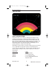
RDR 2100 PG 3/12/07 3:45 PM Page 66 Appendix Maximum Permissible Exposure Levels (MPEL) In order to avoid the envelope in which the radiation level exceeds the U.S. Government standard of 10 mW per square centimeter, all personnel should remain beyond the distance indicated in the illustration below.
RDR 2100 PG 3/12/07 3:45 PM Page 67 Record of Revisions REV. NO. REVISION DATE DATE INSERTED BY Complete Through Rev No. 0 1 9/98 Effective Date: 9/98 Complete Through Rev No.
RDR 2100 PG 3/12/07 3:45 PM Page 68 List of Effective Pages Page Rev i . . . . . . . . . . . . . . . . . . . . . . . . . . . . . . . . . . .Rev 1 ii . . . . . . . . . . . . . . . . . . . . . . . . . . . . . . . . . . .Rev 1 1 . . . . . . . . . . . . . . . . . . . . . . . . . . . . . . . . . . .Rev 1 2 . . . . . . . . . . . . . . . . . . . . . . . . . . . . . . . . . . .Rev 1 3 . . . . . . . . . . . . . . . . . . . . . . . . . . . . . . . . . . .Rev 1 4 . . . . . . . . . . . . . . . . . . . . . . . . . .
RDR 2100 PG 3/12/07 3:45 PM Page 69 List of Effective Pages Page Rev 39 . . . . . . . . . . . . . . . . . . . . . . . . . . . . . . . . . . .Rev 1 40 . . . . . . . . . . . . . . . . . . . . . . . . . . . . . . . . . . .Rev 1 41 . . . . . . . . . . . . . . . . . . . . . . . . . . . . . . . . . . .Rev 1 42 . . . . . . . . . . . . . . . . . . . . . . . . . . . . . . . . . . .Rev 1 43 . . . . . . . . . . . . . . . . . . . . . . . . . . . . . . . . . . .Rev 1 44 . . . . . . . . . . . . . . . . . . . . . . .
RDR 2100 PG Cover 3/12/07 3:43 PM Page 3 Honeywell International Inc. Business & General Aviation One Technology Center 23500 West 105th Street Olathe, Kansas 66061 Telephone: (913) 782-0400 ©1995-1998 Honeywell International Inc. 006-18002-0000 Rev 1 9/98 Printed in U.S.A.