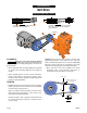
OWNERS MANUAL INSTALLATION AND OPERATING INSTRUCTIONS REPAIR PARTS LIST Self Prime Frame Mounted Centrifugal Pump B4ZRKS B2ZRKL B3TRKS B2XRKS Direct Coupling Drive/ Belt Driven/Hydraulic Drive IMPORTANT For best possible performance and continuous, satisfactory operation, read these instructions before installing your new pump. Should service be required, this manual can be a valuable guide. It should be kept near the installation for ready reference.
Safety First General Information Pump Location General Safety Do not allow pump, piping, or any other system component containing water to freeze. Freezing may damage system, leading to injury or flooding. Allowing pump or system components to freeze will void warranty. Pump approved liquids only with this pump. Periodically inspect pump and system components. Wear safety glasses at all times when working on pumps.
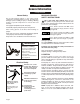
Installation General Information EXAMPLE ONLY NPSHR at this point = 8 Feet NPSHR at this point = 9 Feet B4ZRKS 9.5 Feet total friction loss @ 450 Gallons per minute. 30 20 10 0 10.5 Feet total friction loss @ 550 Gallons per minute. 450 GPM 550 GPM Static Lift = 9.0 Feet Total Friction Loss = 9.5 Feet 9.0 Feet 10.5 Feet 19.5 Feet 150 TDH 2000 RPM 100 NPSHA NPSH in Feet NPSHR Total = 18.5 Feet Theoretical static lift of centrifugal pump at sea level = 34.0 Feet Safety Factor - 6.
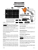
Installation Pump Foundation Typical Installations 1/2" or thicker Sole Plate tapped for hold down bolts Pump or Motor Frame Anchor Bolts ;;;;;;;; @@@@@@@@ ;;;;;;;; @@@@@@@@ ;;;;;;;; @@@@@@@@ ;;;;;;;; @@@@@@@@ ge ina Dra Concrete Foundation Pump or Motor Frame Shims for alignment Steel Channel Anchor Bolt ;;;;; ;; ;; ;;;;; ;; ;; ;;;;;;;; @@@@@@@@ Tack Weld Wedges Various Heights Grout ;;;;;;;; @@
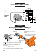
Installation Direct Coupling Drive Shaft Alignment Table I Distance from Centerline 1.00 inch 2.00 inches 3.00 inches 4.00 inches Maximum Allowable T.I.R. 0.035 inches 0.070 inches 0.105 inches 0.140 inches Straight Edge Centerline Fine Alignment Caliper "B" Parallel "A" Angular Course Alignment 2112 1095 Rotating shaft can catch and trap clothing or body. Coupling guard must ALWAYS be in place when pump is running. Coupling guard shown in phantom for pictorial clarity.
Installation Belt Drive Alignment/Proper Belt Tension B B A Incorrect Incorrect A Centerline - A of each shaft and pulley must be parallel for proper alignment. Centerline - B represents center of belt and pulley.This centerline must be straight for proper alignment. Centerline A B B 2113 1095 Centerline A Drive belt can catch and trap clothing or body. Belt guard must ALWAYS be in place when pump is running. Belt guard is not shown for pictorial clarity.
Installation Electric Motor / Hydraulic Motor p p g p prior to installation. Minimum recommended components to protect your pump during 1. Contactor operation. Check all local electrical codes prior to installation. ❶ Contactor ❷ Lightning Arrestor ❸ Loss of Prime Protection ❹ Fuseable Disconnect ❺ Starter 2. Lightning Arrestor 3. Loss of Prime Protection 4. Fuseable Disconnect 5.
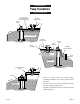
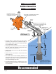
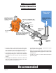
Installation Suction Connection Suction Lift Pump driven by remote power source, direct coupling or pulley/belt connection. Short length of straight pipe after reducer. ( 2 times pipe diameter minimum ) Suction Gauge Straight run, short as possible but at least 6 times pipe diameter ("D") after elbow to stabilize flow. 2114 1095 See foundation section. Standard or long radius elbow. Eccentric Reducer flat side up. Support pipe as required Slope upward to pump.
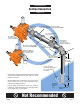
Installation Suction Connection Suction Lift Do not use Concentric Reducer. Concentric Reducer causes high spots along the suction line resulting in air pockets. Do not install valves in suction line. No support or uneven mounting not recommended. Unsupported pipe causes excessive stress on pump and fittings. Excess use of pipe fittings means potential air leaks. Long run not recommended Elbow immediately in front of pump intake not recommended.
Installation Suction Connection When Flooded Suction Exists Water under pressure Pump driven by remote power source, direct coupling or pulley/belt connection. Maintain minumum liquid level to prevent vortexing. Short run of straight pipe after reducer (2 times pipe diameter). Eccentric Reducer flat side up. Suction Gauge 2214 0196 See foundation section. Isolation Valve full open when pumping. Straight run, short as possible but at least 6 times pipe diameter after pipe fitting to stabilize flow.
Installation Suction Connection When Flooded Suction Exists Water under pressure Inverted Eccentric Reducer may result in air pocket. Valve in upward position may trap air. 2215 0196 Do not leave valve partially closed. Check Valve in suction pipe not needed. Unsupported pipe causes excessive stress on pump and fittings. Concentric Reducer may cause air pockets. Miter elbow or short radius elbow not recommended. Do not make elbow connection directly to pump suction.
Installation Discharge Connection Non-Slam or spring loaded check valve. Isolation Valve Isolation valve to permit servicing of check valve or pump. Use Concentric Reducer to mimimize friction losses. Pressure Gauge Discharge pipe diameter at least one nominal pipe size larger than discharge opening in pump. Align piping to minimize flange stress. Support piping as required 2118 1195 • Use pipe, tubing or reinforced hose to make discharge connection.
Installation Discharge Connection Do not use Gate Valve to throttle flow. Avoid check valves that may cause hydraulic shock. Avoid abrupt change in pipe size. Avoid undersized pipe diameter. Do not leave pipe unsupported. 2119 1195 Do not force alignment that can cause flange stresses. • Avoid excess friction loss caused by numerous fittings, insufficient pipe diameter, and sharp turns in pipe run.
Start-up General Information CHECK ROTATION: Before pump is put into operation, rotational direction must be checked to assure proper performance of pump. Refer to illustration below to varify proper rotational direction for each model covered in this manual. Hazardous voltage. Can shock, burn, or cause death. Disconnect power to pump before servicing. Do not attempt any wiring changes without first disconnecting power to pump.
Maintenance General Information LUBRICATION: LIQUID END of pump requires no lubrication. Wear rings, packing rings, and models using a mechanical shaft seal, are lubricated by the liquid being pumped. Do not run dry! BEARING FRAME - add approximately 2 ounces of a lithium-based NGLI No. 2 extra pressure ball bearing grease to each bearing during quarterly inspection. Bearings will run hotter for a brief run-in period after packing which is normal.
Maintenance Packing Ring Replacement Removal Packing Hooks Packing Gland Shaft Packing Ring 2239 0196 2 x Scale 1 1 2 2 • Unfasten hardware holding Packing Gland in place and slide back on shaft to expose packing rings. • Remove packing rings from Stuffing box using two commercially available Packing Hooks as shown. • Slide Lantern Ring (if used) back to expose any remaining rings, including metallic. Remove them in the same manner.
Maintenance General Pump Care ROUTINE MAINTENANCE WINTERIZING A well maintained pumping system will extend the life of the unit and will require fewer repairs. This means less down time which can be very critical when a constant delivery of water is required. If pump is to be out of service for an extended period of time, such as the winter months, the following storage procedures should be followed.
Pump Nomenclature General Information ORDERING REPLACEMENT PARTS: Locate the Berkeley nameplate on the pump, plate is normally on the bearing bracket. Information found on this plate is shown below. To be sure of receiving correct parts, provide all nameplate data when ordering. The BM (Bill of Material) number is most important. Write your nameplate information on the blank nameplate below for future reference as nameplates can become worn or lost. BERKELEY PUMPS MODEL S.N. OR DATE IMPELLER DIA. B.M.
Pump Nomenclature Self Prime Bearing Frame Parts Breakdown Outboard Bearing Bearing Spacer Outer Bearing Cap Inboard Bearing Bearing Frame Bearing Lockwasher Shaft Case Gasket Bearing Lock Nut Inner Bearing Cap Slinger Packing Gland Packing Ring Assembly Impeller Shaft Sleeve 2135N 1195 Lantern Ring Impeller Washer Impeller Screw Suction Flange Gasket Rubber Clack Clamp Pump Case (Volute) Washer Weight Clack Assembly (Check Valve) Suction Flange (Check Valve) B2ZRKL Outboard Bearing Bear
Maintenance Troubleshooting Electrical Drive Pumps PROBABLE CAUSE SYMPTOM A Pump runs, but no water delivered Not enough water delivered Not enough pressure Excessive vibration Abnormal noise Pump stops Overheating X B X X C GROUP I ELECTRICAL D E F X X X X X X X X G H I X X X X X X A X X X X X E F X X X GROUP III SYSTEM A B C X X X X X X X X X X X X X X X CAUSE GROUP II MECHANICAL B C D X X X X X X X X X X CORRECTIVE ACTION I. ELECTRICAL A.
Maintenance Troubleshooting Engine Drive Pumps SYMPTOM Pump runs, but no water delivered Not enough water delivered Not enough pressure Excessive vibration Abnormal noise Pump stops Overheating A X X X B GROUP I ENGINE C D X X X X X X X X X E X X X X X X CAUSE F PROBABLE CAUSE GROUP II MECHANICAL A B C D E X X X X X X X X X X X X X X X X GROUP III SYSTEM A B C X X X X X X X X X X X X F X X X X CORRECTIVE ACTION I. ENGINE A. Speed too low Refer to engine manufacturer’s manual. B.
Maintenance Routine Inspection Record I. QUARTERLY INSPECTION III. QUARTERLY INSPECTION Inspect all system piping connections for leakage or possible misalignment. Check pump foundation for soundness and see that all hold-down bolts are secure. Complete any lubrication requirements as dictated by pump and driver owner’s manual. Inspect packing or mechanical seal for possible replacement. Examine shaft sleeve, if present, for wear and replace if necessary.
Maintenance Notes F00633 Page 23
Berkeley Warranty Berkeley/Wicor Canada, Inc. (“Wicor”) warrants to the original consumer purchaser (“Purchaser”) of its products that they are free from defects in material or workmanship. If within twelve (12) months from the date of installation or twenty-four (24) months from the date of manufacture any such product shall prove to be defective, it shall be repaired or replaced at Berkeley’s/Wicor’s option, subject to the terms and conditions set forth below.