
Operation Manual

8
FIXING THE HOB
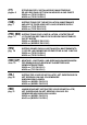
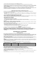
In order to prevent liquids from accidentally leaking into the kitchen unit underneath the appliance is equipped with a special seal. To
put on this seal follow the instructions below very carefully.
1) Stretch out the seal along the edge of the opening, taking care to overlap the joining points. (fig. 2).
2) Insert the hob into the opening in the kitchen unit.
3) With a screwdriver assemble the 4 plates A with the special screw B (fig. 3).
4) Move the plates along and fix them using screw B.
5) Reinsert the part of the seal on the outside of the hob.
IMPORTANT INFORMATION CONCERNING THE INSTALLATION OF THE APPLIANCE
We inform the installer that this hob can be installed by itself, in an isolated position or inserted between two kitchen units or
between one kitchen unit and a wall. Furthermore the back wall and surrounding surfaces must resist a temperature of 65 K.
To prevent the plastic layer which covers the kitchen unit from ungluing, the glue used to join the two surfaces together must
resist temperatures of up to 150 °C
The installation of the appliance must be carried out according to the norms in force of the country concerned and the
appliance must be installed in a well ventilated place.
This appliance is not equipped with devices to remove the products of combustion. The appliance must therefore be
connected following the norms for installation mentioned above. Special attention must be paid to the information below
regarding aeration and ventilation of the premises.
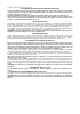
VENTILATION OF THE PREMISES
To guarantee that the appliance works correctly it is necessary that the place where the appliance is installed is continuously ventilated.
The volume of the premises must not be less than 25 m³ and the quantity of air needed must be based on the regular combustion of
gas and on the ventilation of the premises. The natural flow of air will take place through permanent openings made in the wall of the
premises to be ventilated: these openings will be connected to the outside and must have a minimum section of 100 cm² ( see Fig. 4 ).
These openings must be made in such a way that they cannot be obstructed.
POSITION AND VENTILATION
The cooking appliances that use gas must always remove the products of combustion via a hood linked to chimneys, chimney flues or
via a direct connection to the outside ( see Fig. 5A ). If it is not possible to fit a hood it is possible to use a fan, fitted on the window or
facing directly outside, which operates when the appliance is in use. ( see Fig. 5B ). In this way the norms in force of the country
concerned regarding the ventilation of premises are strictly followed.
CONNECTING THE APPLIANCE TO THE GAS SUPPLY
Before connecting the appliance to the gas supply you first need to remove the plastic protective plug for the gas supply
which is inserted under pressure in the gas inlet connection. To remove the plug simply unscrew it.
Then make sure that the details shown on the label on the lower part of the case are compatible with those of the gas supply.
A label on the last page of this manual and on the lower part of the case indicates the conditions for regulating the appliance:
type of gas and pressure used.
IMPORTANT: This appliance must be installed in accordance with the norms in force of the country concerned and it must
only be used in a well-ventilated place.
ATTENTION: Remember that the gas inlet connection for the appliance is threaded 1/2 gas cylindrical male in accordance
with the norms UNI-ISO 228-1. (Fig. 6)
ADAPTING TO DIFFERENT TYPES OF GAS
Before carrying out any maintenance work, disconnect the appliance from the gas and electric supply.
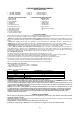
- CHANGING THE NOZZLES FOR USE WITH OTHER TYPES OF GAS:
To change the nozzles of the burners use the following procedure:
Lift up the burners and unscrew the nozzles ( Fig. 7) using an adjustable spanner of 7 mm and change the nozzles with those designed
for the new gas supply according to the information given in TABLE N° 2 shown below.
ATTENTION: After carrying out the changes described above, the technician must put the label corresponding to the new gas
supply on the appliance to take the place of the old label. This label is found in the bag containing spare nozzles.
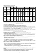
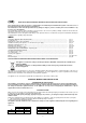
TABLE N°2: Adapting to different types of gas APPLIANCE CATEGORY: II2H3+
Burner
Type of Gas
Pressure
Nozzle
Nominal Charge
Reduced Charge
Diameter
diameter
by-pass 1/100mm
mbar
1/100mm
g/h
l/h
Kw
kcal/h
kw
kcal/h
No saf.
safety
Natural G20
20
77
-
95
1
860
0,3
258
27
27
Auxiliary
Butane G30
28
50
73
-
1
860
0,3
258
27
27
Propane G31
37
50
71
-
1
860
0,3
258
27
27
Semi-
Natural G20
20
101
-
167
1,75
1505
0,44
378
34
31
Rapid
Butane G30
28
66
127
-
1,75
1505
0,44
378
34
31
Propane G31
37
66
125
-
1,75
1505
0,44
378
34
31
Natural G20
20
129
-
286
3
2580
0,75
645
44
42
Rapid
Butane G30
28
87
218
-
3
2580
0,75
645
44
42
Propane G31
37
87
214
-
3
2580
0,75
645
44
42
Natural G20
20
In 70
-
476
5
4300
0,48
413
N.A.
In 34reg
Out 110
out 65reg
Dual
Butane G30
30
In 46
334
-
4,6
3956
0,48
413
N.A.
In 34reg
Out 69
out 65reg
Propane G31
37
In 46
328
-
4,6
3956
0,48
413
N.A.
In 34reg
Out 69
out 65reg
REGULATION OF BURNERS:
1) Regulation of the "MINIMUM" on the burners
To regulate the minimum on the burners carry out the following procedure indicated below: