v.
TABLE OF CONTENTS Table of Contents......................................................................................................................... Introduction.................................................................................................................................... Important Safety Information............................................................................................ Safety Guidelines........................................................................
INTRODUCTION Congratulations!! Thank you for purchasing your new Best Fitness® Elliptical. With state-of-the-art technique, robust frame structure and superior ergonomic design, Best Fitness® Ellipticals set a new standard for excellence. Best Fitness® Ellipticals can improve your quality of life by keeping you fit and healthy, increasing your energy levels and enhancing your lifestyle.
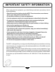
IMPORTANT SAFETY INFORMATION When using exercise equipment, you should always take basic precautions, including the following: • Read all instructions before using the BFE1. These instructions are written to ensure your safety and to protect the unit. • Do not allow children on or near the equipment. • Use the equipment only for its intended purpose as described in this guide. • Do not use accessory attachments that are not recommended by the manufacturer. Such attachments might cause injuries.
SAFETY GUIDELINES Successful resistance training programs have one prominent feature in common ...safety. Resistance training has some inherent dangers, as do all physical activities. The chance of injury can be greatly reduced or completely removed by using correct lifting techniques, proper breathing, maintaining equipment in good working condition, and by wearing the appropriate clothing. 1. It is highly recommended that you consult your physician before beginning any exercise program.
BEFORE YOU BEGIN The Best Fitness® is carefully tested and inspected before shipment. We have shipped the unit in several pieces that require assembly. Carefully unpack the unit in a clear area and lay the pieces on the floor near the area where you plan to use the equipment. Remove the packing material. Do not dispose of the packing material until assembly is complete and the unit is working properly. Place the unit on a clean level surface for assembly.
ASSEMBLY INSTRUCTIONS Assembly of the BFE1 takes professional installers about 1 hour to complete. If this is the first time you have assembled this type of equipment, plan on significantly more time. PROFESSIONAL INSTALLERS ARE HIGHLY RECOMMENDED! However, if you acquire the appropriate tools, obtain assistance, and follow the assembly steps sequentially, the process will take time, but is fairly easy. ASSEMBLY TIPS Read all “Notes” on each page before beginning each step.
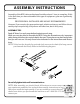
STEP Be careful to assemble all components in the sequence they are presented. 1 A. Carefully lift the Upright Frame Assembly above the front of the Base Frame. B. Attach wire harness as shown. NOTE: A second person is required. C. Slide the Upright Frame onto the Base Frame. D. Insert the hardware as shown.
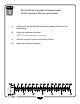
STEP 1 9
STEP Be careful to assemble all components in the sequence they are presented. 2 A. Insert Right Rocker Arm into Right Swing Arm and secure using: One M10x20 Allen Bolt One M10 Washer One M10 Lock Washer B. Insert End Cap into Right Rocker Arm. C. Insert Left Rocker Arm into Left Swing Arm and secure using: One M10x20 Allen Bolt One M10 Washer One M10 Lock Washer D. Insert End Cap into Left Rocker Arm.
STEP 2 11
STEP Be careful to assemble all components in the sequence they are presented. 3 A. Connect the Rocker Arms as shown.
STEP 3 13
STEP Be careful to assemble all components in the sequence they are presented. 4 A. Connect the Right Foot Pedal to the Right Foot Tube using Six M6x16 Phillips Screw B.
STEP 4 15
STEP Be careful to assemble all components in the sequence they are presented. 5 A. Connect the Foot Tubes as shown.
STEP 5 17
STEP Be careful to assemble all components in the sequence they are presented. 6 A. Attach the Water Holder using: Two M8x12 Phillips Bolt B.
STEP 6 19
STEP Be careful to assemble all components in the sequence they are presented. 7 A. Connect the Right Handle Bar using: Three M8x20 Allen Bolt Three M8 Lock Washer B.
STEP 7 21
STEP Be careful to assemble all components in the sequence they are presented. 8 A. Connect the harness from the Console Frame to the Main Frame then secure using: Three M8x65 Allen Bolt Three M8 Washer B. Slide the Net Cover Frame onto the Main Frame and secure using: Two M5x8 Phillips Screw C.
STEP 8 23
CONSOLE OVERVIEW Take a few moments to review the console layout. Below is an overview of the console buttons and their different functions.
CONSOLE OVERVIEW MODE Press the MODE button to set the values for TIME, DISTANCE, CALORIES and PULSE. RESET The RESET button clears all preset values to zero except in user programs. Returns to the Training Mode screen. START/STOP Press the START/STOP button to either start or stop a workout. RECOVERY Press the RECOVERY button to test Heart Rate recovery status. See the Recovery Mode section for further details.
CONSOLE OPERATION SETTING UP THE CONSOLE When plugging in the power cord or after having pressed the TOTAL RESET button, the DISPLAY WINDOW will reset by activating the LCD completely for 2 seconds followed by a long beep. The room temperature will display shortly. Display Window During Reset The DISPLAY WINDOW now will be in Calendar Set Up Mode. The YEAR will be blinking and is ready to be set. Press the UP/DOWN buttons to select the current year.
CONSOLE OPERATION Press the MODE button again and the MINUTES will be blinking and is ready to be set. Press the UP/DOWN buttons to set the minute. Now, pressᇬthe button to exit the Clock Setting Mode and enter Training ᇬ MODE ᇬ Mode. ᇬ ᇬ ᇬ NOTE: IF NO INPUT DATA IS ENTERED, THE DISPLAY WILL SWITCH TO SCREEN SAVER MODE IN 30 SECONDS. TRAINING MODE PROGRAMS Training Mode gives the user several exercise options that allow for a complete and custom workout.
CONSOLE OPERATION MANUAL MODE To access Manual Mode, see the Training Mode Programs section. While in Manual buttons to select a ‘LOAD LEVEL’ from 1 to 16. The Mode, press the UP/DOWN preset load level is 1 and the LOAD readout is flashing on the DISPLAY WINDOW. As the ‘LOAD LEVEL’ increases it will be displayed onto the ‘LOAD LEVEL’ readout on the DISPLAY WINDOW. ‘LOAD LEVEL’ allows for a custom resistance level set by the user.
CONSOLE OPERATION Program Display Program Profile Display After the desired ‘LOAD LEVEL’ is selected, you may preset function values for TIME, buttons. After choosing DISTANCE, CALORIES, and PULSE by using the UP/DOWN the desired function value, press the MODE button to confirm the setting. Press the START/STOP button to start training. During exercise, the user selected preset values will count down. If no preset values were selected, the display values will count up.
CONSOLE OPERATION USER MODE To access User Mode, see the Training Mode Programs section. User Mode allows the user access to create a workout program to tailor fit their exercise requirements. The user can adjust up to 20 workout intervals within the program as well as set customized count-down workout goals. When User Mode is selected, the display will flash the first of twenty customizable workout intervals within the program as well as flash the currently active ‘Load Level’.
CONSOLE OPERATION Use the UP/DOWN buttons to set age. Once the age has been set, press the MODE button to confirm the selection. The display will calculate the preset Heart Rate value automatically according to the age setting entered. The display will show Heart Rate percentages of 55%, 75%, 90% and TARGET according to the user’s weight. Target allows the user to input a custom heart rate goal. Select one of the options by pressing the UP/DOWN buttons.
CONSOLE OPERATION WATT MODE To access Watt Mode, see the Training Mode Programs section. Watt Mode allows the user to output a constant power during a workout. This means that if you pedal quickly, the resistance will decrease, if you pedal slowly the resistance will increase to maintain the Watt value entered. When Watt Mode is selected, the preset value of 120 (watts) is flashing. Use the UP/ DOWN buttons to set the target value from (10-350).
CONSOLE OPERATION SLEEP MODE If there is no signal input (you stop pedaling and do not press any buttons for four consecutive minutes, the backlit display will turn off. During Sleep Mode, the display will show the current room temperature, clock and calendar. All workout data is preserved in RAM memory. Sleep Mode Display WAKE UP MODE To bring the console into Wake Up Mode, press any button or begin pedaling to turn the display on.
MONITORING YOUR HEART RATE To obtain the greatest cardiovascular benefits from your exercise workout, it is important to work within your target heart rate zone. The American Heart Association (AHA) defines this target as 60% -75% percent of the Maximum Heart Rate. The Maximum Heart Rate may be roughly calculated by subtracting the user’s age from 220. The Maximum Heart Rate and aerobic capacity naturally decreases as the user ages.
MONITORING YOUR HEART RATE 90% 75% 55% Percentage of Maximum Heart Rate AGE 189 180 171 162 153 144 157 150 135 126 142 135 117 108 127 120 115 110 112 105 104 99 97 90 93 88 82 77 71 66 10 20 30 40 50 60 70 80 Beats Per Minute FITNESS SAFETY The Heart Rate chart indicates average rate zones for different ages. A variety of different factors (including medication, emotional state, temperature and other conditions) can affect the target heart rate zone that is best for you.
Serial Number is Located on the Frame Model Name : BFE1 Purchase Date: _______________________________ Serial Number: _______________________________ 1900 S. Des Plaines Ave. Forest Park, Il 60130 1 (800) 556-3113 Hours: M-F 8:30 - 5:00 CST www.BestFitness.com Copyright 2009. Best Fitness. All rights reserved. Best Fitness reserves the right to change design and specifications when we feel it will improve the product.