INSTALLATION INSTRUCTIONS HB0303 CPD9M SERIES ! INTENDED FOR OUTDOOR DOMESTIC COOKING ONLY ! READ AND SAVE THESE INSTRUCTIONS INSTALLER: LEAVE THIS MANUAL WITH HOMEOWNER. HOMEOWNER: USE AND CARE INFORMATION ON PAGES 8 AND 9. BEST; Hartford, Wisconsin www.BestRangeHoods.com 800 558-1711 BEST; Drummondville, QC, Canada www.BestRangeHoods.com 866 737-7770 To register your product online or for additional information visit www.BestRangeHoods.com 23648 rev.
! WARNING ! TO REDUCE THE RISK OF FIRE, ELECTRIC SHOCK OR INJURY TO PERSONS, OBSERVE THE FOLLOWING: WARNING TO REDUCE THE RISK OF INJURY TO PERSONS IN THE EVENT OF A RANGE TOP GREASE FIRE, OBSERVE THE FOLLOWING*: 1. Use this unit only in the manner intended by the manufacturer. If you have questions, contact the manufacturer at the address or telephone number listed in the warranty. 1. SMOTHER FLAMES with a close-fitting lid, cookie sheet or metal tray, then turn off the burner.
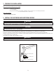
1. PREPARE THE INSTALLATION NOTE: Before proceeding to the installation, check the contents of the box. If items are missing or damaged, contact the manufacturer. Make sure that the following items are included: - Power Pack - Accessories • Baffle filters with handles • 10” round adapter • Bag of parts including: 1 wire clamp, 2 waterproof wire connectors, 9 no. 8 x 5/8” type A screws, 2 no. 8-18 x 3/8” screws, 1 suction cup. Parts sold separately: • Blower assembly model P12NA. 2.
3. CUSTOM HOOD PREPARATION ! WARNING When building a custom hood, always follow all applicable construction codes and standards. ! WARNING The custom wood hood must be positively secured to wall studs or other wooden framework behind the wall. Make sure it is capable of supporting its own weight and the weight of the power pack. Failure to do so may cause personal injury or damage to surfaces below. The custom hood must be constructed to fit the size and shape of the power pack.
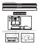
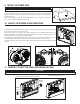
4. REMOVE THE FILTERS Remove the tape from the filters. Remove the filters from the power pack, and set aside. It is recommended to start with the center one(s). HD1112 5. REMOVE THE GREASE DRIP RAIL A B A. Lift and rotate the grease drip rail to disengage it from the bottom panel. B. Slide grease drip rail all the way to the left or right and lift the opposite end to disengage the other end from the bottom panel. Remove it from the power pack and set aside for later use. HD1111 6.
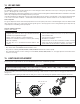
7. INSTALL THE ADAPTER Remove the 10-inch round adapter from inside the power pack, and install it on the top using 2 no. 8-18 x 3/8” Phillips screws, and the small notches around the adapter. HJ0185 8. CONNECT WIRING ! WARNING Risk of electric shock. Electrical wiring must be done by qualified personnel in accordance with all applicable codes and standards.
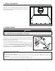
9. INSTALL THE POWER PACK CAUTION Take care not to kink ducting when installing the power pack. Using the provided no. 8 x 5/8” screws, install the power pack inside the custom hood. Start with 2 screws in the front corners, then install 4 screws for the sides and use the remaining screws to finalize securing the front power pack. (See figure at right for mounting screw specific locations.) Make sure the adapter enters the ducting.
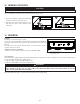
12. REINSTALL THE FILTERS CAUTION Remove the protective plastic film covering the filters before installing them. It is recommended to install side filters first and to finish with center one(s). 1 2 1. Insert the end with the spring of the baffle filter into the front channel of the power pack. 2. Raise the other end toward the inside of power pack and insert in the grease drip rail of the power pack. HD0526 13. OPERATION BLOWER The blower is operated using two controls.
14. USE AND CARE Baffle Filters The baffle filters should be cleaned frequently. Use a warm detergent solution. Wash more often if your cooking style generates greater grease — like frying foods or wok cooking. Remove baffle filters by pushing them towards the front of power pack and rotating filters downward. Baffle filters are dishwasher safe. Allow filters to dry completely before reinstalling them in the power pack. Clean all-metal filters in the dishwasher using a non-phosphate detergent.
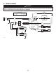
16. WIRING DIAGRAM ! WARNING Risk of electrical shock. Electrical wiring must be done by qualified personnel in accordance with all applicable codes and standards. Before connecting wires, switch power off at service panel and lock service disconnecting means to prevent power from being switched on accidentally.
17. SERVICE PARTS B M C REPLACEMENT PARTS AND REPAIRS In order to ensure your unit remains in good working condition, you must use Broan-NuTone genuine replacement parts only. Broan-NuTone genuine replacement parts are specially designed for each unit and are manufactured to comply with all the applicable certification standards and maintain a high standard of safety.
18. WARRANTY FIVE-YEAR LIMITED WARRANTY FOR BEST® PRODUCTS Warranty Period and Exclusions: Broan-NuTone, LLC (the “Company”) warrants to the consumer purchaser of its product (“you”) that the product (the “Product”) will be free from material defects in the materials or its workmanship for a period of five (5) years from the date of original purchase (or such longer period as may be required by applicable law) or a period of two (2) years from the date of service for any labor provided on the Product.
INSTRUCCIONES DE INSTALACIÓN HB0303 SERIE CPD9M ! EXCLUSIVAMENTE PARA COCINAS DOMÉSTICAS EXTERIORES ! LEA ESTAS INSTRUCCIONES Y GUÁRDELAS INSTALADOR: ENTREGUE ESTE MANUAL AL PROPIETARIO DE LA CASA. PROPIETARIO: INFORMACIÓN SOBRE UTILIZACIÓN Y CUIDADO EN LAS PÁGINAS 8 Y 9. BEST; Hartford, Wisconsin www.BestRangeHoods.com 800-558-1711 BEST; Drummondville, QC, Canada www.BestRangeHoods.com 866-737-7770 Para registrar su producto en línea o para obtener más información, visitar nuestro sitio www.
! ADVERTENCIA ! ADVERTENCIA PARA REDUCIR EL RIESGO DE LESIONES CORPORALES EN EL CASO DE QUE ARDA LA GRASA EN LA PARTE SUPERIOR DE LA COCINA, SIGA ESTAS INDICACIONES*: PARA REDUCIR EL RIESGO DE INCENDIO, DESCARGA ELÉCTRICA O LESIÓN CORPORAL, RESPETE LAS SIGUIENTES INDICACIONES: 1. Utilice esta unidad únicamente de la forma en que indica el fabricante. Si tiene cualquier pregunta, póngase en contacto con el fabricante en la dirección o el teléfono que aparecen en la garantía. 2.
1. PREPARACIÓN DE LA INSTALACIÓN NOTA: Antes de comenzar la instalación, verificar el contenido de la caja. Si alguna pieza falta o está dañada, póngase en contacto con el fabricante. Compruebe que el conjunto para la instalación contiene los elementos siguientes: - Grupo de alimentación - Accesorios • Filtros deflectores con manilla • Adaptador redondo de 10 pulgadas • Bolsa de piezas: 1 abrazadera para hilos, 2 conectores impermeables de hilos, 9 tornillos tipo A n.o 8 x 5/8 pulg, 2 tornillos n.
3. PREPARACIÓN DE LA CAMPANA A MEDIDA ! ADVERTENCIA Siga siempre todos los códigos y normas de construcción aplicables al construir una campana a medida. ! ADVERTENCIA La campana de madera debe fijarse bien a los montantes murales o a otra estructura de madera situada detrás de la pared. Asegúrese de que pueda soportar su propio peso y el peso del grupo de alimentación. De no ser así, podrían producirse lesiones personales o daños en las superficies inferiores.
4. DESMONTAJE DE LOS FILTROS Retire la cinta de los filtros. Saque los filtros del grupo de alimentación y póngalos aparte. Se aconseja empezar por el filtro o filtros centrales. HD1112 5. DESMONTAJE DEL RIEL DE VERTIDO DE LA GRASA A B A. Levante y gire el riel de vertido de la grasa para separarlo del tablero inferior. B. Deslice el riel completamente a la izquierda o a la derecha y levante el extremo contrario para desprenderlo del tablero inferior.
7. INSTALACIÓN DEL ADAPTADOR Retire el adaptador redondo de 10 pulgadas desde el interior del grupo de alimentación, e instálelo en la parte superior utilizando 2 tornillos Phillips n.° 8-18 x 3/8” y las pequeñas muescas alrededor del adaptador. HJ0185 8. CONEXIÓN DEL CABLEADO ! ADVERTENCIA Riesgo de choque eléctrico. La conexión eléctrica debe hacerla personal competente con arreglo a los códigos y normas en vigor.
9. INSTALACIÓN DEL GRUPO DE ALIMENTACIÓN PRECAUCIÓN Procure no doblar los tubos al instalar el grupo de alimentación. Utilice los tornillos n.° 8 x 5/8” provistos para instalar el grupo de alimentación en la campana. Empiece por los 2 tornillos en las esquinas delanteras; a continuación, utilice 4 tornillos para los lados y emplee los demás tornillos para sujetar el grupo de alimentación por delante (véase la figura de al lado para la ubicación exacta de los tornillos).
12. VUELVA A INSTALAR LOS FILTROS PRECAUCIÓN Retire la película protectora de plástico que cubre los filtros antes de instalarlos. Se aconseja instalar primero los filtros laterales y terminar por el o los centrales. 1. Introduzca el extremo del filtro con resorte en el canal delantero del grupo de alimentación. 1 2 2. Levante el otro extremo hacia el interior del grupo de alimentación e introdúzcalo en el riel de vertido de la grasa. HD0526 13.
14. USO Y CUIDADO Filtros deflectores Los filtros deflectores deben limpiarse con frecuencia. Utilice una disolución de detergente con agua templada. Lávelos con mayor frecuencia si su tipo de cocina genera más grasa (alimentos fritos o cocina con wok). Retire los filtros empujándolos hacia la parte delantera del grupo de alimentación y girándolos hacia abajo. Las placas de los filtros pueden lavarse en el lavavajillas.
16. DIAGRAMA ELÉCTRICO ! ADVERTENCIA Riesgo de choque eléctrico. La conexión eléctrica debe hacerla personal competente con arreglo a los códigos y normas en vigor. Antes de conectar los hilos, corte la alimentación en el tablero de servicio y bloquee los medios de desconexión para impedir que la corriente se conecte accidentalmente.
17. PIEZAS DE REPUESTO B SUSTITUCIÓN DE PIEZAS Y REPARACIÓN M L C Para que la unidad se conserve en buen estado, debe usar repuestos genuinos de Broan-NuTone únicamente. Estas piezas se han diseñado especialmente para cada unidad y se han fabricado conforme a las normas de certificación aplicables y un elevado nivel de seguridad. El uso de repuestos de otros fabricantes podría causar daños graves y reducir radicalmente el desempeño de la unidad, causando así fallas prematuras.
18.