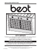
INSTALLATION INSTRUCTIONS CPD SERIES Suitable for use in damp locations when installed in a GFCI protected branch circuit. Intended for outdoor covered patio or lanai area. VQ0009 ! INTENDED FOR DOMESTIC COOKING ONLY VQ0009 ! READ AND SAVE THESE INSTRUCTIONS INSTALLER: LEAVE THIS MANUAL WITH HOMEOWNER. HOMEOWNER: USE AND CARE INFORMATION ON PAGES 12 to 13. BEST®; Hartford, Wisconsin www.BestRangeHoods.com 800-637-1453 BEST®; Drummondville, QC, Canada www.BestRangeHoods.
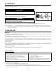
! VQ0009 WARNING ! VQ0009 WARNING TO REDUCE THE RISK OF FIRE, ELECTRIC SHOCK OR INJURY TO PERSONS, OBSERVE THE FOLLOWING: TO REDUCE THE RISK OF INJURY TO PERSONS IN THE EVENT OF A RANGE TOP GREASE FIRE, OBSERVE THE FOLLOWING*: 1. Use this unit only in the manner intended by the manufacturer. If you have questions, contact the manufacturer at the address or telephone number listed in the warranty. 1. 2.
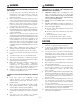
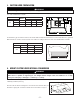
- CPD HOOD LINER SYSTEM (HIGH MODEL 437 CAPACITY ROOF CAP) MODEL 441 (10’’ ROUND WALL CAP) MODEL 418 (10” ROUND ADJUSTABLE ELBOW) MODEL 410 (10” ROUND DUCT — 2 FT.
1. INSTALL DUCTWORK AND ELECTRICAL WIRING INSTALLATION Install proper-sized ductwork, elbows and roof or wall cap for the type of blower you are installing. Use 10” round ductwork. Use metal foil duct tape to seal duct joints. The minimum hood liner distance above cooktop must not be less than 36’’. Distances over 36” are at the installer and users discretion. Run 3-wire power supply cable to installation location. Its length should extend at least 4 feet below the bottom of the custom hood.
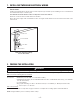
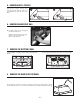
3. CUSTOM HOOD PREPARATION VQ0010 ! WARNING When building a custom hood, always follow all applicable construction codes and standards. The custom hood must be constructed to fit the size and shape of the CPD hood liner. See chart and illustration for details.
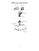
5. REMOVE BAFFLE FILTERS Remove tape on filters. Remove filters from power pack and set aside. It is recommended to start with the center filters. 1 2 6. REMOVE GREASE DRIP RAIL A A. Lift grease drip rail to disengage it from the bottom panel. (Blower shown is for reference only and does not represent actual blower in this product.) HD0291 7. REMOVE THE BOTTOM PANEL Disassemble bottom panel, lift up and out, and set aside. Using a Phillips screwdriver, remove both bottom filter filler panels.
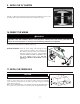
9. INSTALL THE 10” ADAPTER Using (4) no. M4 x 6 screws from parts bag, assemble the adapter on the top of the hood liner. Seal all joints with metal foil duct tape to eliminate air leaks. MOUNTING SCREW LOCATION HJ0026 10. CONNECT THE WIRING VQ0010 ! WARNING Risk of electric shock. Electrical wiring must be done by qualified personnel in accordance with all applicable codes and standards.
12. REINSTALL BOTTOM PANEL Re-install filter filler panels as shown. Lift the bottom panel and engage the hood liner metal tabs in bottom panel slots. Secure the bottom panel to the hood liner using its screws. RETAINING SCREW LOCATIONS RETAINING SCREW LOCATIONS BOTTOM BOTTOM VIEW 13. REINSTALL GREASE DRIP RAIL A A. Center the grease drip rail over the bottom panel edge and drop it in place. (Blower shown is for reference only and does not represent actual blower in this product.) HD0291 14.
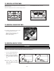
15. LIGHT BULBS This power pack must use shielded halogen lamps (120 V, 50 W PAR16 with GU10 base, 2 for CPDI362 and 4 for the CPDI482 & CPDI602), included. NOTE: Before using lamps, remove shipping tape on them (if present). VQ0010 ! WARNING In order to prevent the risk of personal injury, do not install a lamp not suitable for use in enclosed fixtures. 1 2 1. Install the lamps by placing the bulb leads into their grooves in the socket. 2. Gently push upwards and turn clockwise until secure.
17. OPERATION Always turn your hood liner on before you begin cooking to establish an air flow in the kitchen. Let the blower run for a few minutes to clear the air after you turn off the range. This will help keep the whole kitchen cleaner and brighter. COOKTOP LIGHTING (HALOGEN) The halogen lighting is controlled by the dial. • POSITION 1: OFF • POSITION 2: LOW • POSITION 3: HIGH • POSITION 4: OFF • Use 120 V, 50 W, MR16 with GU10 base or PAR16 with GU10 base, shielded halogen lamps (included).
18. WIRING DIAGRAM MODEL CPDI362SB MODELS CPDI482SB & CPDI602SB 19. WARRANTY WARRANTY ONE-YEAR LIMITED WARRANTY Broan-NuTone LLC (“Broan-NuTone”) warrants to the original consumer purchaser of its products that such products will be free from defects in materials or workmanship for a period of one year from the date of original purchase. THERE ARE NO OTHER WARRANTIES, EXPRESS OR IMPLIED, INCLUDING, BUT NOT LIMITED TO, IMPLIED WARRANTIES OF MERCHANTABILITY OR FITNESS FOR A PARTICULAR PURPOSE.
20. SERVICE PARTS Best CPD Series 1 2 3 4 12 11 5 6 10 7, 8 9 KEY NO. PART NO. DESCRIPTION QTY.
DIRECTIVES D'INSTALLATION SÉRIE CPD Peut être installé dans des endroits humides si branché sur un circuit à disjoncteur de fuite à la terre (GFCI). S’utilise à l’extérieur sur les terrasses couvertes ou vérandas. POUR USAGE DOMESTIQUE SEULEMENT VQ0009 ! VQ0009 ! LIRE CES DIRECTIVES ET LES CONSERVER INSTALLATEUR : VEUILLEZ REMETTRE CE MANUEL AU PROPRIÉTAIRE. PROPRIÉTAIRE : VOIR LE MODE D'UTILISATION ET D'ENTRETIEN AUX PAGES 12 ET 13. BEST®; Hartford, Wisconsin www.BestRangeHoods.
! VQ0009 AVERTISSEMENT ! VQ0009 AVERTISSEMENT AFIN DE RÉDUIRE LES RISQUES D'INCENDIE, DE CHOC ÉLECTRIQUE OU DE BLESSURES CORPORELLES, VEUILLEZ OBSERVEZ LES DIRECTIVES SUIVANTES : OBSERVEZ LES CONSIGNES SUIVANTES AFIN DE RÉDUIRE LES RISQUES DE BLESSURES ORPORELLES EN CAS D'INCENDIE CAUSÉ PAR DE LA GRAISSE SUR LE PLAN DE CUISSON* : 1. 1. 2. 3. 4. 5. 6. 7. 8. 9. 10. 11. 12. N'utilisez cet appareil que de la manière prévue par le fabricant.
- CPD SYSTÈME DE HOTTE MODÈLE 437 (CAPUCHON DE TOIT À GRANDE CAPACITÉ) À DOUBLE PAROI MODÈLE 441 (CAPUCHON MURAL ROND DE 25 CM [10 PO]) MODÈLE 418 (COUDE ROND AJUSTABLE DE 25 CM [10 PO]) MODÈLE 410 (CONDUIT ROND DE 25 CM [10 – SECTIONS DE 61 CM [2 PI]) PO] ADAPTATEUR ROND DE 25 CM (10 PO) (FOURNI AVEC LA PAROI DE LA HOTTE) PAROI DE HOTTE CPD VENTILATEUR DOUBLE 3,4 CM3/MIN (1200 PI3/MIN) (INCLUS) - 15 - -
1. INSTALLATION DES CONDUITS ET DU CÂBLAGE ÉLECTRIQUE INSTALLATION Installez des conduits, coudes et capuchon de toit ou mural de la taille appropriée pour le type de ventilateur que vous installez. Utilisez du conduit rond de 25 cm (10 po). Scellez tous les joints avec du ruban pour conduit. La distance minimale de la paroi de hotte au-dessus de la surface de cuisson ne doit pas être inférieure à 91 cm (36 po).
3. PRÉPARATION D’UNE HOTTE SUR MESURE ! VQ0010 AVERTISSEMENT Lors de la fabrication d’une hotte sur mesure, suivez les codes du bâtiment et les normes en vigueur. La hotte sur mesure doit être fabriquée de manière à convenir à la taille et à la forme de la paroi de hotte CPD. Voir le tableau et l’illustration pour plus de détails.
5. ENLEVER LES FILTRES DE DÉFLECTEURS Enlevez le ruban adhésif des filtres. Enlevez les filtres de la hotte et mettezles de côté. Il est conseillé de commencer par les filtres du centre. 1 2 6. ENLEVER LA GOUTTIÈRE À GRAISSES A A. Soulevez la gouttière pour la dégager du panneau du fond. (Le ventilateur, montré, est pour référence seulement et ne représente pas le véritable soufflerie dans ce produit.) HD0291 7.
9. INSTALLER L’ADAPTATEUR DE 25 CM (10 PO) À l’aide des quatre (4) vis M4 x 6 du sachet de pièces, assemblez l’adaptateur sur le dessus de la paroi de la hotte. Scellez tous les joints avec du ruban à conduit pour éviter les fuites d’air. EMPLACEMENT DES VIS DE MONTAGE HJ0026 10. RACCORD DU CÂBLAGE VQ0010 ! AVERTISSEMENT Risque de choc électrique. Les branchements électriques doivent être effectués par un personnel compétent, conformément aux normes et aux codes en vigueur.
12. REPOSER LE PANNEAU INFÉRIEUR Reposez les panneaux de filtre tel qu'illustré. Soulevez le panneau inférieur et engagez les languettes métalliques de la paroi de la hotte dans les fentes du panneau. Fixez le panneau inférieur à la paroi de la hotte à l’aide de ses vis. EMPLACEMENT VUE EMPLACEMENT DES VIS VUE DE DESSOUS DES VIS DE DESSOUS 13. REPOSER LA GOUTTIÈRE À GRAISSES A A. Centrez la gouttière à graisses au-dessus du rebord du panneau inférieur et déposez-le en place.
15. AMPOULES Cette hotte utilise des ampoules halogènes à écran (120 V, 50 W, PAR16 à culot GU10, deux pour le modèle CPDI362 et quatre pour les modèles CPDI482 et CPDI602) (incluses). REMARQUE : Avant d’utiliser les ampoules, enlevez le ruban adhésif d’emballage (s’il y a lieu). VQ0010 ! AVERTISSEMENT Pour éviter les risques de blessure personnelle, n’utilisez pas d’ampoules qui ne conviennent pas aux luminaires fermés. 1 2 1.
17. FONCTIONNEMENT Mettez toujours la hotte en marche avant de cuisiner afin d'établir une circulation d'air dans la cuisine. Laissez la hotte fonctionner quelques minutes après l'arrêt de la cuisinière afin de nettoyer l'air. Ceci contribuera à la propreté de toute votre cuisine. ÉCLAIRAGE (HALOGÈNE) L’éclairage halogène est commandé par un cadran.
250VCA 2 PIÈCES NOIR NOIR NOIR BLEU BLEU VIOLET NOIR NOIR BLEU VIOLET VIOLET CONDENSATEUR 22 uF ROUGE ROUGE VIOLET VIOLET BLEU BLANC VERT BLEU VIOLET NOIR BLEU NOIR GRIS BRUN BLEU ROUGE BLANC NOIR BOÎTIER NOIR BLEU ROUGE NOIR NOIR JAUNE ROUGE NOIR VIOLET VIOLET BLEU BLANC NOIR BOÎTIER VERT GRIS BRUN BLEU BLANC NOIR BLANC VERT MOTEUR MOTEUR BLANC JAUNE ROUGE BLANC BLEU GRIS BRUN BLANC BLANC BLANC BLEU GRIS BRUN BLANC BLEU GRIS BRUN BLANC VERT VERT BOÎTIE
20.
INSTRUCCIONES DE INSTALACIÓN SERIE CPD Adecuado para usarse en sitios húmedos cuando se instala en un circuito de derivación protegido GFCI. Diseñado para patio exterior cubierto o techado. VQ0009 ! INDICADO SOLAMENTE PARA COCINAR EN CASA VQ0009 ! LEA Y CONSERVE ESTAS INSTRUCCIONES INSTALADOR: DEJE ESTE MANUAL CON EL PROPIETARIO DE LA VIVIENDA. PROPIETARIO DE LA VIVIENDA: INFORMACIÓN DE USO Y CUIDADO EN LAS PÁGINAS 12 a 13. BEST®; Hartford, Wisconsin www.BestRangeHoods.
! VQ0009 ADVERTENCIA PARA REDUCIR EL RIESGO DE INCENDIOS, DESCARGAS ELÉCTRICAS O LESIONES PERSONALES, SIGA LAS SIGUIENTES PRECAUCIONES: 1. 2. 3. 4. 5. 6. 7. 8. 9. 10. 11. 12. ! VQ0009 PARA REDUCIR EL RIESGO DE LESIONES A PERSONAS EN CASO DE UN INCENDIO PRODUCIDO POR GRASA EN UNA ESTUFA, OBSERVE LO SIGUIENTE*: Use la unidad solo de la manera indicada por el fabricante. Si tiene preguntas, comuníquese con el fabricante a la dirección o al número telefónico que se incluye en la garantía.
- SISTEMA DE RECUBRIMIENTO DE CAMPANA MODELO 437 (TAPA DE TECHO DE ALTA CAPACIDAD) MODELO 441 (TAPA REDONDA DE PARED, DE 10 PULG. (25 CM)) MODELO 418 (CODO REDONDO AJUSTABLE DE 10 (25 CM)) PULG. MODELO 410 (CONDUCTO REDONDO DE 10 PULG. (25 CM) – SECCIONES DE 2 PIES (61 ADAPTADOR REDONDO DE 10 PULG.
1. INSTALE LOS CONDUCTOS Y EL CABLEADO ELÉCTRICO INSTALACIÓN Instale conductos, codos y tapa para techo o muro de tamaño adecuado al tipo de ventilador que está instalando. Utilice un conducto redondo de 10 pulg. (25 cm). Use cinta para conductos metálica para sellar las uniones de conductos. La distancia mínima del recubrimiento de la campana sobre la superficie de la estufa no debe ser menor de 36 pulg. (91 cm). Las distancias mayores de 36 pulg.
3. PREPARACIÓN DE LA CAMPANA A LA MEDIDA VQ0010 ! ADVERTENCIA Cuando arme una campana a la medida, siga siempre todos los códigos y normas de construcción correspondientes. La campana a la medida debe construirse para adecuarse en tamaño y forma al recubrimiento de la campana CPD. Consulte los detalles en el cuadro y la ilustración. RECUBRIMIENTO PESO TOTAL ATRÁS DIMENSIONES DE LA CAMPANA 3” DE LA CAMPANA SERIE MODELO *A *B CL 51/8” 2” C C CPDI362 73 LB (33 kg) 22 1⁄2” (57.
5. RETIRE LOS FILTROS DEFLECTORES Retire la cinta de los filtros. Saque los filtros del paquete de potencia y deje a un lado. Se recomienda comenzar con los filtros centrales. 1 2 6. RETIRE EL RIEL PARA ESCURRIMIENTOS DE GRASA A A. Levante el riel para escurrimientos de grasa para desmontarlo del panel inferior. (El soplador, que se muestra, es sólo para referencia y no representa la real soplador en este producto.) HD0291 7.
9. INSTALE EL ADAPTADOR DE 10 PULG. (25 CM) Utilizando cuatro (4) tornillos M4 x 6 de la bolsa de piezas, arme el adaptador en la parte superior del recubrimiento de la campana. Selle todas las uniones con cinta para conductos metálica para eliminar fugas de aire. UBICACIÓN DE LOS TORNILLOS DE MONTAJE HJ0026 10. CONECTE EL CABLEADO VQ0010 ! ADVERTENCIA Riesgo de descarga eléctrica.
12. REINSTALE EL PANEL INFERIOR Reinstale los paneles de relleno del filtro tal como se muestra. Levante el panel inferior y acople las lengüetas metálicas del recubrimiento de la campana en las ranuras del panel inferior. Asegure el panel inferior al recubrimiento de la campana utilizando sus tornillos. UBICACIONES DE LOS TORNILLOS DE RETENCIÓN UBICACIONES DE LOS TORNILLOS DE RETENCIÓN VISTA VISTA INFERIOR INFERIOR 13. REINSTALE EL RIEL PARA ESCURRIMIENTOS DE GRASA A A.
15. BOMBILLAS Este paquete de potencia debe usar lámparas de halógeno protegidas (120 V, 50 W PAR16 con base GU10, 2 para el CPDI362 y 4 para los CPDI482 y CPDI602), que se incluyen. NOTA: Antes de usar las lámparas, retire la cinta de envío colocada sobre ellas (si la hubiera). VQ0010 ! ADVERTENCIA Con el fin de prevenir el riesgo de lesiones personales, no instale una lámpara que no sea adecuada para accesorios cerrados. 1.
17. FUNCIONAMIENTO Encienda siempre el recubrimiento de la campana antes de comenzar a cocinar para establecer un flujo de aire en la cocina. Deje el ventilador funcionando unos cuantos minutos para despejar el aire después de apagar la estufa. Esto ayudará a mantener toda la cocina más limpia y brillante. LUZ DE LA ESTUFA (HALÓGENO) Las luces de halógeno se controlan con el indicador de carátula.
NEGRO 250VCA 2 PIEZAS BLANCO NEGRO AZUL NEGRO AZUL VIOLETA NEGRO AZUL ROJO ROJO VIOLETA CONDENSATOR 22 uF NEGRO BLANCO VIOLETA VIOLETA AZUL BLANCO NEGRO VERDE AZUL VIOLETA NEGRO NEGRO BLANCO CAJA NEGRO BLANCO NEGRO GRIS MARRÓN AZUL ROJO NEGRO AZUL BLANCO AMARILLO ROJO NEGRO NEGRO VIOLETA AZUL BLANCO NEGRO VERDE VIOLETA AZUL MARRÓN AZUL VERDE BLANCO AZUL GRIS MARRÓN BLANCO GRIS AZUL GRIS MARRÓN BLANCO BLANCO AMARILLO ROJO CAJA BLANCO MOTOR MOTOR AZUL GRI
20. PIEZAS DE SERVICIO Best Serie CPD 1 2 3 4 12 11 5 6 10 7, 8 9 CLAVE N.º DE PIEZA 1 97018874 2 3 CANT. (ANCHO DEL PAQUETE DE POTENCIA) N.º DESCRIPCIÓN 36 pulg. (91 cm) 48 pulg. (122 cm) 60 pulg. (152 cm) ADAPTADOR REDONDO DE 10 PULG. (25 CM) 1 1 1 98010930 98010931 RIEL PARA GRASA DE 36 PULG. (91 CM) RIEL PARA GRASA DE 48 PULG. (122 CM) Y 60 PULG.