BFB-3000 Set Up and Operations Manual [Version 3.
BFB-3000 Set Up and Operations Manual 1 Introduction Thank you for purchasing your BFB-3000. Before first use, the BFB-3000 needs careful setting up.
BFB-3000 Set Up and Operations Manual 2 Table of Contents 1 Introduction ................................................................................................................... 2 2 Table of Contents ........................................................................................................... 3 3 Manual symbols ............................................................................................................. 5 4 How this manual works ...............................
BFB-3000 Set Up and Operations Manual 7 Print the first model ..................................................................................................... 47 7.1 Test print ................................................................................................................. 47 7.2 Essential post-print operations ................................................................................ 48 7.2.1 Bed flatness ....................................................................
BFB-3000 Set Up and Operations Manual 3 Manual symbols CAUTION: notes to prevent damage to the machine. DANGER: notes to prevent injury to the operator.
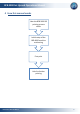
BFB-3000 Set Up and Operations Manual 4 How this manual works How the BFB-3000 3D printing process works Initial setup of the BFB-3000 machine and testing First print Links for further printing Document No: D100253 6
BFB-3000 Set Up and Operations Manual 5 Process overview – how the BFB-3000 works Before reading this section, please ensure that the unpacking instructions have been completed. 5.
BFB-3000 Set Up and Operations Manual 5.2 Tool kit Model removal tool Side cutters Hex drivers 1.5mm Allen Wrench Ø0.
BFB-3000 Set Up and Operations Manual 5.3 Creating a 3D model CAD software BFB “Axon” Draw your object in your 3D modelling package1 Load your model into Axon to automatically process the file. Save as… *.STL Save as… *.BFB 1 Most CAD packages export to STL format. However, STL quality depends on the CAD package. Poor quality STLs may need repairing before loading into “Axon”. STL fixing programs are readily available (e.g. NetFabb).
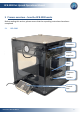
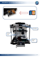
BFB-3000 Set Up and Operations Manual Extruders Delivery tubes Filament reels Document No: D100253 10
BFB-3000 Set Up and Operations Manual Hot-end The extruders pull filament from the reel via the delivery tubes and drive through a hot-end to produce a thin molten filament of plastic. The extruder draws each layer with this filament. After each layer is produced the bed increments down so that a new layer can be drawn on top of the last, building up the 3D model. A second (optional) extruder automatically prints support filament for printing overhanging-features.
BFB-3000 Set Up and Operations Manual 6 Initial set-up Follow all the steps in this section to ensure that the printer is correctly setup before printing. 6.1 Remove existing prints We do test prints on each BFB-3000 as part of our quality control. We leave these on the print bed to show that the printer has been checked, and to demonstrate some basic prints. Remove any previous prints with the model removal tool. Slide the edge between the bed and the first layer to remove the entire print.
BFB-3000 Set Up and Operations Manual 6.2 Check the bed is clear of any build material Clean: no build material debris Ensure that all build material is completely removed from the bed. Use the model removal tool to remove any stuck-fast tracks. It is normal for prints to leave marks on the bed, and for the model removal tool to lightly scratch the surface of the bed. This will not affect the printer’s operation.
BFB-3000 Set Up and Operations Manual 6.3 Check the bed is fitted correctly Ensure that bed is correctly fitted to the printer. The three bed bolt heads should sit flush in the countersinks. If not, remove the bed, then refit it - as shown in the next two sections.
BFB-3000 Set Up and Operations Manual 6.3.1 Remove the bed Tip: removal is easier if the bed is near the bottom of the machine. If it is too high, you can manually lower the z-axis (see “Manual move”, page 18).
BFB-3000 Set Up and Operations Manual 6.3.2 Fit the bed Tip: fitting is easier if the bed is near the bottom of the machine. If it is too high, you can manually lower the z-axis (see “Manual move”, page 18). Check all bolt heads are fitted correctly (see “Check the bed is fitted correctly”, page 14).
BFB-3000 Set Up and Operations Manual 6.4 Power up Connect the power supply from the control panel into the power socket shown in Figure 1. Turn the supply on. Turn the control box on using the power switch shown in Figure 1.
BFB-3000 Set Up and Operations Manual 6.5 Manual move Get familiar with moving the axes around: Ensure that the bed is fitted properly to the machine (see “Check the bed is fitted correctly”, page 14). Using the buttons on the control panel (see “Power up”, page 17) select the ‘Manual move’ function and press enter: > RUN FILE EXTRUDER MAPPING MANUAL MOVE EXTRUDER CONTROL HOME TOOL HEAD SETTINGS Use X, Y and Z buttons to move each axis respectively (axes designated in Figure 2, page 19).
BFB-3000 Set Up and Operations Manual “Home” Position + X + Y - - Z + Figure 2: Axis designation for the BFB-3000 Document No: D100253 19
BFB-3000 Set Up and Operations Manual 6.6 Check the hot-end nozzles are clean from plastic debris Ensure that the metal nozzle tips are clean from any plastic debris. All tips should be clearly visible. Nozzle tip clearly visible, and free of any plastic debris If not: Lower the bed to make access to the nozzles easy. Position the extruders in approximately the middle of the machine (see “Manual move”, page 18), to make access to the nozzles easy.
BFB-3000 Set Up and Operations Manual 6.7 Check the bed is level To get a good print, the bed must be level. We make every effort to level the bed before the machine leaves our factory. However, the bed may move in transit, therefore it is essential to check that the bed is still level. The print bed is mounted on three sprung bolts which allow adjustment of the bed height in three places.
BFB-3000 Set Up and Operations Manual The ‘Level Bed’ function moves the extruder carriage around the corners of the bed so the operator can adjust the bed bolts to achieve a level bed. Check the bed is fitted correctly (page 14).
BFB-3000 Set Up and Operations Manual Press the X+ and X- buttons to automatically move the carriage around the corners of the print bed (view on-screen instructions for more movement options). During each movement along the side of the bed, observe from the side of the machine any change in distance between the bed and extruder’s hot-end as it moves along. Adjust bed bolts to make extruders move parallel to the bed.
BFB-3000 Set Up and Operations Manual Adjust the height of the bed bolts to make each side level using the 3mm hex driver from the toolkit. Underneath each of the 3 bed bolts is a locking nut which must be loosened with the 8mm spanner before the bolt can be adjusted. Loosen locking nut to adjust bolt. It may take several movements of the extruder, and consequent bolt adjustments to ensure that the bed is level.
BFB-3000 Set Up and Operations Manual Ensure that axes are checked from the appropriate side of the machine (to better judge flatness): PHOTOGRAPHS TAKEN FROM ABOVE View the movements in the X axis from the front of the machine. BACK FRONT View the movements in the Y axis from the sides of the machine.
BFB-3000 Set Up and Operations Manual 2 mm Press Z+ to reduce the gap between the hot end and bed to approximately 2 mm. This will enable finer levelling. Repeat the levelling process. Caution: Observe each extruder movement. The nozzle should not touch the bed. Moving the extruder with the nozzle touching the bed will damage the nozzle and the bed. If the nozzle touches the bed, immediately lower the bed using the Z- button. Finally, check the centre location of the bed by pressing Y+.
BFB-3000 Set Up and Operations Manual Remember to lock the 3 bed bolts in position by tightening the lock nut under each, using the 8mm spanner. Whilst tightening the nut, make sure that the bolt does not spin by holding it in position with the 3mm hex driver, from the top side of the bed. Tighten nut to lock bolt into position.
BFB-3000 Set Up and Operations Manual 6.8 Check the bed is referenced to the extruder nozzles After levelling the bed, the nozzles must be set to the correct height, to ensure that the first printed layer sticks properly (if the nozzle is too high the filament will not stick to the bed, if the nozzle is too low the bed may block the nozzle). Use the ‘Set Z Height’ function to accurately adjust the height of the nozzle for the first layer.
BFB-3000 Set Up and Operations Manual Caution: If the nozzle is pushed too hard against the bed, the nozzle will be forced into the bed for the whole first layer of printing. This will damage the nozzle and the bed. Ensure that setting the nozzle against the bed does not compress the bed springs.
BFB-3000 Set Up and Operations Manual Pressing Enter (X+) will save the setting to the printer’s memory which is retained when the power is turned off. The Z offset value will be applied each time the printer is homed. Pressing Escape will exit the function without saving the value.
BFB-3000 Set Up and Operations Manual 6.9 Load the extruders 6.9.1 Load the filament Before loading a reel, the end of the filament must be prepared to prevent damage to the delivery tubes. This procedure is essential to prevent any damage to the delivery tubes, which may in turn block a nozzle. Cut the end of the filament at 45° from both sides to produce a point. Using sandpaper, remove all sharp edges. The tip should feel smooth.
BFB-3000 Set Up and Operations Manual Reel positions for each extruder are indicated below: Delivery tubes for each extruder run from right to left, as indicated below: Tube for Extruder 3 Tube for Extruder 2 Tube for Extruder 1 Reel position for Extruder 1 Reel position for Extruder 2 Reel position for Extruder 3 Figure 5: Reel positions and delivery tubes Document No: D100253 32
BFB-3000 Set Up and Operations Manual Load the type of materials into their reel positions according to the number of extruders in the BFB-3000: Number of extruders in the BFB-3000 Material for Extruder 1 Material for Extruder 2 1 ABS or PLA 2 ABS PLA 3 ABS PLA Example for this section: BFB-3000 with two extruders.
BFB-3000 Set Up and Operations Manual 3 Push filament out of the end of the delivery tube Check the filaments exit the tubes at the correct extruders: Extruder 1 Document No: D100253 Extruder 2 (Extruder 3) 34
BFB-3000 Set Up and Operations Manual Remove the pressure bearings (below) on the extruders 4 Use the 4mm hex driver from the toolkit Pressure bearing assembly 5 Document No: D100253 Use pliers to push the filaments into the white tube for each extruder, as far as it will go (approximately 10 cm) 35
BFB-3000 Set Up and Operations Manual 6 Re-attach the pressure bearings onto the extruders. 7 Tighten the pressure bearing springs until they are fully bound. (they will be adjusted from this position later.) 8 Document No: D100253 Ensure filaments run on the middle (smaller) pressure bearings. If not, move the bearings around using the nose of the pliers until they snap into position.
BFB-3000 Set Up and Operations Manual 6.9.2 Extruder control Make sure all extruders are loaded. Use ‘Manual move’ (page 18) to move the extruders to the centre of the machine, and lower the bed. This makes it easy to clean any purged material.
BFB-3000 Set Up and Operations Manual Recommended maximum extrusion temperatures for materials: Material Extrusion temperature (°C) ABS 260 PLA 195 Note: Extruders share power, therefore an extruder will heat up quicker if it is the only extruder with a high target temperature. 6.9.3 Purge the extruder Ensure filaments are loaded into the extruders, as defined in the section “Load the filament”, page 31. Make sure the springs on the extruder pressure bearings are fully compressed.
BFB-3000 Set Up and Operations Manual Pressure bearing bolt 4mm hex driver from toolkit Observe the end of the nozzle. A thin bead of molten plastic should come out of the nozzle. Depending on how far the filament was loaded into the extruder, this could take several minutes. Thin filament of plastic Allow material to purge for a few seconds before reducing the RPM to 0. Repeat for each extruder. Turn the machine off to allow the nozzles to cool.
BFB-3000 Set Up and Operations Manual 6.10 Start a print Make sure all items below have been checked. This is essential to guarantee that the print works.
BFB-3000 Set Up and Operations Manual 6.11 Print a successful raft The raft supports the model during printing: Model Raft It is essential that a good raft is printed to guarantee a good build. Therefore the height of the hot-end nozzle over the bed for the first layer is critical: If the nozzle is too far away from the bed, the filament will not stick to the bed If the nozzle is too low it will not be able to extruder the filament, and there is a risk of damage to the bed and the nozzle.
BFB-3000 Set Up and Operations Manual SIDE VIEW END VIEW COMMENTS NOZZLE TOO HIGH: Not enough pressure on the filament into the bed, therefore small contact area between filament and bed. Raft may detach in mid print. OK: Filament pushed into the bed slightly to maximise surface area contact with bed, but still maintain extrusion flow. NOZZLE TOO LOW: Not enough clearance for the filament to be extruded, damaging either the extruder or the bed.
BFB-3000 Set Up and Operations Manual 6.11.1 Print the raft check file To make sure your printer is correctly setup, you will need to print the raft check file. This file is already included on the SD card supplied in your toolkit. Make sure materials are loaded as per “Load the filament” (page 31). Follow the section “Start a print” (page 40) to print the preloaded raft check file (on the SD card supplied in your toolkit) relevant to the material loaded into Extruder 1 (see table below).
BFB-3000 Set Up and Operations Manual 6.11.2 Examine the raft check file RAFT MAGNIFICATION NOTES NOZZLE TOO HIGH: Wavey tracks, or tracks narrower than 1.2 mm (use vernier calipers to check). See “Perfect the raft” (page 46). OK NOZZLE TOO LOW: Tracks sides pushed over neighbouring tracks. See “Perfect the raft” (page 46).
BFB-3000 Set Up and Operations Manual 6.11.3 Potential problems If the raft pad appears damaged, match the imperfection to the two scenarios below, and follow the corrective action suggested. Note that there may be some imperfections in the raft, but that the process is very forgiving and even the images shown below will generally not spoil a full print. 6.11.3.1 Track ripping Track ripping: can be caused by a dirty nozzle snagging a track, and ripping it in the direction of the extruder.
BFB-3000 Set Up and Operations Manual 6.11.4 Perfect the raft If analysis of the raft check file yields any problems, you will need to re-examine some of the setup stages: ERROR CORRECTIVE ACTION Nozzle too high See “Check the bed is referenced to the extruder nozzles” (page 28) to adjust the height at which the nozzle starts printing. Nozzle to low See “Check the bed is referenced to the extruder nozzles” (page 28) to adjust the height at which the nozzle starts printing.
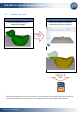
BFB-3000 Set Up and Operations Manual 7 Print the first model 7.1 Test print To get your BFB-3000 printer up and running as quickly as possible, we have already loaded a .BFB file of a duck for you to immediately make. Make sure materials are loaded as per “Load the filament” (page 31). Follow “Start a print” (page 40) to print the Duck file using the file on the SD card relevant to the number of extruders on your BFB-3000 (see table below).
BFB-3000 Set Up and Operations Manual 7.2 7.2.1 Essential post-print operations Bed flatness New beds will distort slightly due to heating from the extruder. Check bed flatness with a straight edge (e.g. ruler) after each print: Slight ‘bowing’ can be detected using the edge of a ruler. If the bed is bowed downwards (even slightly), turn the bed over (page 15 and 16) to point the bow of the bed upwards for the next print, as shown below.
BFB-3000 Set Up and Operations Manual 7.2.2 Empty material waste bin After each print you will need to empty the nozzle wipe box Lower the bed (see “Manual move”, page 18) to access the nozzle wipe box. Remove the waste box from the machine and dispose of the plastic deposits. Re-install the waste box back into the machine, ready for your next print.
BFB-3000 Set Up and Operations Manual 8 Further printing Now your printer is set up, you will need to visit our website at www.bitsfrombytes.com to: Download and install Axon software (illustrated in page 9). Check for free updates - we issue updates regularly to continually improve printing performance.
BFB-3000 Set Up and Operations Manual 9 Further operations 9.1 SD card notes All .BFB files (exported from Axon) must be saved to the root of the SD card. Any files in folders on SD card will not be displayed on the BFB-3000. The SD card must be no larger than 2 Gb. 9.2 Reloading the extruders See “Load the extruders” (page 31) for all references: Remove pressure bearing. Heat up the nozzle to extrusion temperature (see Extruder control, page 37).
BFB-3000 Set Up and Operations Manual 9.3 Notes on materials 9.3.1 Properties Material Properties ABS High toughness. Non-degradable. Do not print area larger than 100 mm square – ABS has relatively high shrinkage on cooling, and some geometries for larger prints are prone to warping. PLA Similar strength to ABS. Biodegradable above 60 °C. 9.3.2 Soluble support structure For overhanging model features, Axon automatically generates support material.
BFB-3000 Set Up and Operations Manual 9.4 Control panel functions After turning the BFB-3000 on, the control panel presents the main menu (below). > RUN FILE EXTRUDER MAPPING MANUAL MOVE EXTRUDER CONTROL HOME TOOL HEAD SETTINGS Use the Z buttons to scroll up and down the menu. Press X+ to enter a function. Press Escape to return to the main menu. The following sections describe all the functions. 9.4.1 Run file See “Start a print” (page 40). 9.4.
BFB-3000 Set Up and Operations Manual Use the Y buttons to change the mapping. Press X+ to save, or Escape to quit without saving. Axon builds the BFB file using Gcodes. The file is readable with any text viewing program. Some basic Gcode knowledge is required in order to identify which extruder is used for a particular purpose i.e. raft, model or support material. It is also a requirement to identify which material the Gcode extruders are running by observing the temperatures in use. E.g.
BFB-3000 Set Up and Operations Manual 9.4.3 Manual move See “Manual move”, page 18. 9.4.4 Extruder control See “Extruder control”, page 37. 9.4.5 Home tool head Push ‘Enter’ to move all axes to their home position. Make sure the bed is in position before homing the tool head. The bed contains a sensor necessary for homing. Without the sensor, the machine will drive the bed frame into the waste disposal stand-offs. Repeated collisions will damage the machine. 9.4.
BFB-3000 Set Up and Operations Manual 9.4.6.1 Extruder offsets Extruder offsets defines the position of extruders 2 and 3 in the BFB-3000, relative to extruder 1. Settings here should only be changed after performing a nozzle calibration print. Visit our website to download the calibration procedure and determine the offsets values. > Extruder Extruder Extruder Extruder 2 2 3 3 X Y X Y -44.30 0.00 -88.60 0.00 Use the Z buttons to select the extruders. Use the Y buttons to alter the values.
BFB-3000 Set Up and Operations Manual 9.4.7.1 Set bed type The bed design in the machine dictates how the machine operates. > V2 Black composite V1 Clear perspex Use the Z buttons to select the bed type. Press X+ to save, or Escape to quit without saving. If the wrong bed is selected, the machine will be unable to home its zaxis and will damage itself.
BFB-3000 Set Up and Operations Manual 9.4.7.2 General settings General settings are designed for advanced use. > Ignore G92 Enable Hopping Yes Yes Use the Z buttons to select the option. Press X+ to save, or Escape to quit without saving. Incorrect general settings will severely affect the BFB-3000 print quality. Do not change any general settings without fully understanding each setting first. See the following sections for general setting explanations.
BFB-3000 Set Up and Operations Manual 9.4.7.2.1 Ignore G92 The “ignore G92” setting is required because of the previous method of managing extruder offsets which involves using the Gcode G92 command. The user was required to determine the extruder 2 offset value through printing the calibration print. The calculated offset value was then entered into Axon. During Gcode generation, Axon inserts a G92 offset command to offset the carriage by the user calculated offset amount.
BFB-3000 Set Up and Operations Manual 9.5 9.5.1 Maintenance operations Updating your printer Visit our website at www.bitsfrombytes.com to check for free upgrades. This may include: Firmware (the software inside the control box) Hardware (mechanical improvements) 9.5.2 Adjusting the nozzle wipe The nozzle wipe should sit slightly higher than the height of the nozzle tip, so that when the nozzle is moved over the wipe, the wipe brushes over the nozzle tip.
BFB-3000 Set Up and Operations Manual To adjust the height of the nozzle wipe, remove the nozzle wipe box and loosen the M3 nuts and bolts on the back of the wipe using the 2.5mm hex driver supplied in the toolkit. Use the reference holes to gauge the adjustment, and ensure that the nozzle wipe is horizontal. Reference holes M3 nuts Retighten the M3 nuts, replace the nozzle wipe box and re-check nozzle wipe position.
BFB-3000 Set Up and Operations Manual 9.5.3 Fine adjustment to level the nozzles Nozzles must be level for a reliable print. If one nozzle is lower than the other, it may damage the print. To evaluate if the nozzles are level: Make sure the bed is flat (see “Bed flatness", page 48) Check the bed is level (page 21) Check the hot-end nozzles are clean from plastic debris (page 20). It is common to mistake dirty nozzles as not being level – especially if the polymer in the extruder is transparent.
BFB-3000 Set Up and Operations Manual The ø 0.5 mm nozzle orifice only has 1.0 mm thickness. Remove as little material as possible to achieve level nozzles. Do not remove more than 1.0 mm, otherwise the orifice will begin to widen, and the nozzle will be permanently damaged. When all nozzles are level, stop sanding. Manually turn the ø 0.5 mm drill bit (supplied in the toolkit) 2 revolutions to remove any burrs in the orifice from the sanding process.
BFB-3000 Set Up and Operations Manual 9.5.4 Handling a ground-out filament If a pressure bearing is poorly assembled, or the nozzle suffers from a blockage (e.g. printing too close to the bed), the back of the filament may be ground out by the extruder drive shaft. The drive shaft will then be unable to push the filament down into the nozzle, preventing the extruder from extruding. This is normally indicated by a fast build-up of plastic dust around the pressure bearing.
BFB-3000 Set Up and Operations Manual Cut filament using side cutters Heat extruder to melt plastic using “Extruder control”, page 37. Remove loaded section using pliers Examine the removed filament to confirm the cause: Ground-out section Normal drive shaft teeth marks Reload the filament, as per “Load the extruders” (page 31) taking care to prepare the tip of the filament as specified.
BFB-3000 Set Up and Operations Manual 9.5.5 Handling snapped filament in the delivery tube If filament snaps in more than one place in the delivery tube, the tube needs to be flushed of any trapped broken sections before the filament can be reloaded. Broken section of filament Remove all readilyavailable sections of filament Also remove filament from extruder end, as per “Handling a ground-out filament”, page 64.
BFB-3000 Set Up and Operations Manual Unclip delivery tube from back panel at all points Pull out delivery tube full out of bottom bracket Bring delivery tube up to top of the machine Document No: D100253 67
BFB-3000 Set Up and Operations Manual Pull delivery tube out of the energy chain from extruder end completely removing it from the machine Energy chain Prepare an end of filament from the reel – rounding the edges as per standard filament loading procedure (page 31) This will be used to push any trapped segments out of the delivery tube, and support the tube when re-threading back into the machine Document No: D100253 68
BFB-3000 Set Up and Operations Manual Push reel filament down delivery tube, from the nut end Hold tube in a coil to match the natural bend of the filament, making it easier to push out the trapped segments of filament. Once all the trapped segments have been pushed out, continue to push the reel filament through so that approximately 5 cm protrudes at both ends. Then cut the reel filament to detach the arrangement from the reel.
BFB-3000 Set Up and Operations Manual Tape up on non-nut end of the tube so that the filament cannot move in the tube. Insert the taped end back down inside the energy chain from the extruder end Push the tube all the way back down the energy chain. You may need to move the extruders around to massage the tube through.
BFB-3000 Set Up and Operations Manual On exiting the energy chain, remove the tape Re-clip the delivery tube against the back panel Run the delivery tube under the second steel bar at the back of the machine.
BFB-3000 Set Up and Operations Manual Remove the support filament from the delivery tube Position the nut-end of the tube so that the nut sits comfortably on the extruder body Finally, reload filament, as “Load the filament”, page 31 Document No: D100253 72
BFB-3000 Set Up and Operations Manual 9.6 Troubleshooting Please visit our website at www.bitsfrombytes.com to use our troubleshooting guides. 9.7 Troubleshooting Please visit our website at www.bitsfrombytes.com to raise a support ticket. 9.8 Specifications Please visit our website at www.bitsfrombytes.com to view specification sheets on the BFB-3000.