
User Manual


7
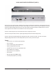
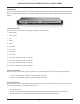
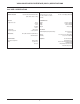
VOCIA VOICE OVER IP INTERFACE (VOIP-1) REAR PANEL
Rear Panel Information
Power
The VOIP-1 requires a 24V DC power source to operate, and is capable of accepting dual 24V DC inputs for redundancy. Both power
sources may be connected concurrently, however each must be capable of supporting the full 30-Watt load of the unit (inputs are not
intended to load-share). Loss or return of either power source will not result in an interruption to normal operation as long as one of these
power sources remains functional. Monitoring of power sources is selectable via the Vocia Software.
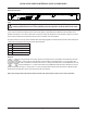
The power connector is a four-way 5.08mm standard header with mating pluggable screw terminal block with cable restraint. When power
is present the corresponding front panel green power LED will illuminate.
Pin Function
1 DC Power 1 24V(+)
2 DC Power 1 24V(-)
3 DC Power 2 24V(+)
4 DC Power 2 24V(-)
Device ID
The rotary ID switches on the VOIP-1 give the unit a unique Device ID. The switches are in hexadecimal format. All
VOIP-1 units must have a unique Device ID to function within a Vocia Paging World (i.e. it is not possible to have
two VOIP-1 units with the same Device ID of hex 07). To assign a Device ID of hex 07, turn the MSB switch on 0 and
leave the LSB switch to 7. To create an ID of hex B7, turn the MSB switch to B and turn the LSB switch to 7. Device
ID switches should be set using a 0.1 inch (2.5mm) to 0.12 inch (3.0mm) at blade screwdriver. More information on setting IDs and the
hexadecimal numbering scheme used in Vocia can be found in the Vocia Help File.
Please note: changes made to the Device ID while connected to the network require a power cycle in order to take effect.
Caution – Due to potential energy hazard, connections to the Aux Power 24V DC inputs must be
made by qualied electrician or other qualied person as required to conform with all local codes.
851.0386.900