® Model ET 5000W Operation and Service Manual Patented 25 /16 ”B L AL Load Capacity: 5000 lbs ® The ET 5000W ESCALATE TRAILER offers ground level roll-on loading and roll-off unloading of equipment with non-tilting lowering deck. The hydraulic lift deck allows one person to load and unload equipment. Contents SAFETY ............................................................... 2 SPECIAL FEATURES .......................................... 2 SPECIFICATIONS.............................................
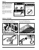
SAFETY WARNING Warnings and Cautions WARNING Stand clear of trailer while deck is being raised or lowered. Moving deck will create pinch points causing serious crushing injury. Observe all warning labels on the trailer. The trailer warning labels are shown here as a reminder. Other warnings and cautions are included in this manual. Stand clear of trailer while deck is being lowered. Contact with trailer deck will cause serious crushing injury.
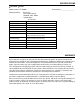
SPECIFICATIONS ESCALATE® TRAILER Model Number ET 5000W Manufactured by: Serial Number ________________ Bil-Jax, Inc. 125 Taylor Parkway Archbold, Ohio 43502 419.445.9675 Specifications Rated Capacity 5000 lbs. (2268 kg) max. Weight (Empty) 2540 lbs. (1152 kg) Overall Width 101 in. (256.5 cm) Overall Length 204 in. (518.2 cm) Overall Height (Bed Raised) 38-1/2 in. (97.8 cm) Bed Height (Raised) 17-1/2 in. (44.5 cm) Bed Size (Flat Surface) 61 in. wide x 96 in. long (154.9 cm wide x 243.
This page intentionally left blank 4
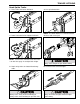
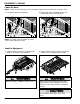
TRAILER HITCHING Hook Up the Trailer 1. Raise trailer and loosen ball latch. 2. Line up ball with hitch. 2 5/ 1 6” LL BA 2 16 5/ ” LL BA NOTE: The trailer hitch uses a 2 5/16 inch ball. 3. Lower hitch onto ball and tighten ball latch. 2 5/ 1 6” 4. Raise and secure jack. LL BA 2 5/ 16 ” LL BA NOTE: Trailer frame should be level when hitch is on ball. See page 11 to adjust hitch height. Always raise and pin the jack before towing. 5. Hook safety chains and attach breakaway cable.
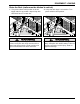
EQUIPMENT LOADING Lower the Deck NOTE: Trailer must be hitched to vehicle according to page 5 before lowering or raising the deck. 1. Turn power switch to ON position. 2. Hold toggle switch in DOWN position. Lift latch handle and push handle back. NOTE: The trailer frame should be on a level surface when lowering the deck. Load the Equipment 1. Load equipment so that the resulting tongue weight is 15 to 20% of the total load. ” 16 ” 5/ 2 5/ 16 2 2.
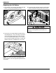
EQUIPMENT LOADING Raise the Deck (trailer must be hitched to vehicle) 1. Turn power switch to ON position and hold toggle switch in up position. Stop raising deck when deck latch is on latch bar. 2. Verify that deck latch is on latch bar. Turn power switch to OFF position. Make sure people are away from the trailer before raising the deck. Keep hands and feet away from deck and rails. Hands and feet can get crushed between the deck and frame. If not clamped, the deck may fall during travel.
SERVICE Tire Maintenance Wheel Torque Requirements At least once each week, use an accurate tire pressure gage to check the air pressure in all four trailer tires. Inflate to the pressure recommended by the tire manufacturer (located on the tire). It is extremely important to apply and maintain proper wheel mounting torque on your axle. Wheel nuts should be retorqued after 50 miles and 100 miles and periodically there after.
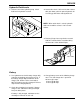
SERVICE Hydraulic Fluid Levels 1. Remove cover from hydraulic pump. Check fluid level in hydraulic reservoir. 2. Lower trailer deck. If oil level is below 3 inches with deck down, add 1/2 quart of hydraulic oil. Use BP type HLP-46 or 10w hydraulic oil. NOTE: When trailer deck is raised, hydraulic fluid level should be at least 1/2 of reservoir volume. 3. Remove fill cap from surge brake reservoir. Add DOT 3 brake fluid as needed to bring fluid level to 1/2-inch below fill port.
SERVICE Replacing the Lift Rollers 1. On a paved, level surface, pull trailer onto 4x6 blocks. Jack up and unhitch the trailer. 2. Lower the deck until the front or rear lift rollers can be removed from the roller access holes. 3-1/2 The deck must be supported by the paved surface or shoring before the lift rollers are removed. 3. Loosen the setscrews that prevent the rollers from backing out. The setscrews are located on the trailer frame where the rollers thread in.
SERVICE Adjusting the Hitch Height The trailer frame and deck should be level for equipment loading and unloading. If the trailer hitch is too high or too low when hitched to the towing vehicle, readjust the hitch height. 1. Unhitch trailer. Remove hitch mounting bolts and nuts. 2 5 Adjust hitch height when trailer is empty. Use jack to aid in hitch adjustment. 2. Install hitch in new position. 2 5 Failure to install and tighten all hitch mounting screws may cause serious equipment damage.
PARTS LIST Model ET 5000W ESCALATE® TRAILER, Hitch Section Item No. Part No.
PARTS LIST 2 1 5 13 4 4 6 3 2 8 7 9 31 28 30 32 35 33 28 34 28 27 28 29 36 27 4 L AL 2 26 B 6” 5/1 37 15 14 22 22 12 7 21 24 11 10 8 17 24 25 20 23 18 16 19 ® Model ET 5000W ESCALATE TRAILER, Hitch Section 13
PARTS LIST Model ET 5000W ESCALATE® TRAILER, Lift Section Item No. 14 Part No. Description Qty 1 0090-0428 Washer, SAE Flat, ¾ 2 2 B07-06-1035 Bar, Deck Latch 1 3 0090-0147 Pin, Cotter, 1/8 x 1-¼ 2 4 0090-0689 Nut, Nylon Lock, 1-8 5 5 0090-0429 Washer, SAE Flat, 1 2 6 0090-0902 Screw, Cap, 1-8 x 7 1 7 B07-07-5010 Bar, Lift 1 8 B07-10-1087 Spacer, 1-7/32 in.
PARTS LIST 4 35 1 21 2 5 3 8 5 32 8 31 33 30 34 6 7 9 1 4 28 29 11 27 10 26 12 11 14 25 24 14 28 36 4 15 11 23, 23A 13 16 13 18 22 12 17 21 20 19 Model ET 5000W ESCALATE® TRAILER, Lift Section 15
PARTS LIST Model ET 5000W ESCALATE® TRAILER, Deck and Frame Section Item No. Part No. 1 B12-00-0094 2 Qty Item No.
PARTS LIST 1 2 3 48 3 4 4 3 6 5 3 6 47 7 8 53,53A,53B 52 9 41 42 12 13,13A, 13B,13C 11 43 10 44 36 43 49 42 50 46 15 14 22,22A,22B,22C 18 21 19 24 20 45 40 39 51, 51A, 51B 38 32 37 32 24A 25 33 34 23 16 17 28 26 29 30 32 32 35 31 27 33 Model ET 5000W ESCALATE® TRAILER, Deck and Frame Section 17
PARTS LIST Model DB-1343 Hydraulic Pump Assembly Item No. 18 Part No. Description Qty 1 B02-15-0119 Coupling, SAE 9T-20/40 1.26 1 2 B02-15-0128 Ball, 0.375 Steel, G50 1 3 B02-15-0091 Seal, Shaft 0.500 x 1.00 x 0.25 1 4 B02-15-0201 Breather, Plastic 1 5 B02-15-0093 Washer, 0.338 x 0.625 x 0.60 Steel 3 6 B02-15-0166 Washer, Lock, 0.255 x 0.485 x 0.062 1 8 B02-15-0061 Magnet, Plumbing 1 9 B02-15-0121 Filter, 149 Micron 1.50 x 1 1 10 B02-15-0122 Motor, DC - 12V, 1T, Std.
PARTS LIST Model DB-1343 Hydraulic Pump Assembly 19
125 Taylor Parkway Phone 419-445-9675 Archbold, OH 43502 Fax 419-445-0367