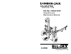
LOG SPLITTER VERTICAL TYPE 20 TON Part No.
VERTICAL TYPE LOG SPLITTER This equipment is designed and manufactured in compliance with the duties, responsibilities, and standards set forth for manufacturers in the ANSI B71.7 standard in effect at the time of manufacture. This equipment will meet or exceed applicable OSHA codes and ANSI B71.7 standards when used in accordance with ANSI B71.7 and all other manufacturer’s recommendations.
Table of Contents 1 2 3 4 5 6 7 Safety........................................................................................1 1 Introduction..................................................................1 2 Before Operation.........................................................3 3 During Operation .........................................................4 4 Fire Prevention............................................................5 5 Towing Safety.................................................
List of Illustrations Figure 3-1. Figure 3-2. Figure 3-3. Figure 3-4. Figure 3-5. Figure 5-1. Figure 5-2. Figure 6-1. Figure 6-2. Figure 6-3. Figure 6-4. Figure 6-5. Figure 6-6. Operation Zone.................................................................13 Operator Controls .............................................................14 Function Interrupt Control Assembly...............................15 Wedge Control Assembly ................................................15 I-Beam Lock Pin ..........
1 Safety 1 INTRODUCTION Familiarity and proper training are required for the safe operation of mechanical equipment. Equipment operated improperly or by untrained personnel can be dangerous. Read the operating instructions in this manual and become familiar with the location and proper use of all controls. Inexperienced operators should receive instruction from someone familiar with the equipment before being allowed to operate the machine.
This information is not intended to be all inclusive and is to be followed in the use of bil-jax equipment only. For any questions concerning the safe use of this equipment, call 419.445.9675 before operating. Safety Notes This manual contains DANGERS, WARNINGS, CAUTIONS, and NOTES that must be followed to prevent the possibility of improper service, damage to the equipment, or personal injury. DANGER Dangers warn of equipment operation that could lead to personal injury or death.
2 BEFORE OPERATION Ensure the following general safety precautions are observed before operating the splitter. • Read and understand this manual completely. For your own safety and the safety of others, become familiar with the splitter BEFORE attempting to operate it. Failure to do so, or any deliberate misuse of the splitter, may result in serious injury or death.
3 • DO NOT operate without wearing protective hearing devices. • NEVER wear loose clothing, jewelry or gloves that could be caught by moving parts. Keep clothing away from all moving parts of splitter. Wear proper head gear to keep loose hair away from moving parts. DURING OPERATION Ensure the following general safety precautions are observed during the operation of the splitter. 4 • DO NOT attempt to operate the splitter from outside of the operation zone.
4 • NEVER place hand, foot, or other body part between log and wedge or log and stripper. When loading splitter, place hands on the sides of the log. • DO NOT attempt to split logs across the grain. Logs split in this manner may snap away from the wedge with enough force to cause injury. • NEVER attempt to split more than one log at a time. One may fly out and cause injury. • NEVER attempt to load splitter while wedge is in motion. • DO NOT step across the splitter while engine is running.
5 • ALWAYS have a fire extinguisher available during splitter operation as a precaution against flying sparks. • NEVER operate the splitter near flames or sparks. Gasoline is extremely flammable. • DO NOT smoke while operating or refueling the splitter. Gas fumes are explosive and extremely flammable. • NEVER refuel a hot or running engine. Allow engine to cool before refueling. • Only refuel splitter outdoors in a clear area free of fumes and spilled fuel. ALWAYS use an approved fuel container.
6 • ALWAYS allow for splitter length when turning corners, parking, crossing intersections, and in all other driving situations. • ALWAYS use caution when backing up splitter. It is easy to jack-knife the splitter when backing up. • NEVER allow anyone to ride on the splitter during towing. • NEVER transport cargo or logs on splitter during towing. • ALWAYS disconnect the splitter from the towing vehicle before operation.
• 7 Use only manufacturer approved parts. Parts must comply with strict manufacturer specifications. Only parts purchased from the manufacturer can be guaranteed to comply with these specifications. HYDRAULIC SAFETY Ensure the following safety precautions are observed when any hydraulic system maintenance is being performed on the splitter. WARNING Hydraulic system under high pressure. Escaping fluid can have enough force to penetrate skin causing serious personal injury, even death.
8 DAMAGED EQUIPMENT POLICY Safety Statement At bil-jax, we are dedicated to the safety of all users of our products. Therefore, all bil-jax log splitters are designed, manufactured and tested to comply with current applicable Federal OSHA and ANSI codes and regulations. Damage Policy There may be occasions when a bil-jax log splitter is involved in an incident that results in structural damage to the splitter. This can seriously compromise the ability of the splitter to perform in a safe manner.
10
2 Introduction 1 GENERAL DESCRIPTION The Lumber-Jax 20 Ton Vertical Log Splitter, model AU5V20H manufactured by bil-jax, is designed and built to split square cut logs up to 24 inches long and up to 8 inches in diameter. The splitter is powered by an 8 horsepower Honda GX240 engine. The gas engine drives a 2-stage hydraulic pump that delivers up to 2500 psi to the hydraulic ram cylinder. During operation, a steel wedge attached to the cylinder moves downward splitting the cut log.
2 SPECIFICATIONS Lumber-Jax 20 Ton Vertical Log Splitter Model Number AU-5V20H Serial Number __________________ Manufactured by: bil-jax, inc. 125 Taylor Parkway Archbold, Ohio 43502 419.445.8915 Table 2-1. Specifications 12 Force 20 tons Engine Honda GX240, 8 hp Pump 2-Stage, 11 gpm (0.7 lps) Cylinder 4 in. bore x 2 in. rod (10.2 x 5.1 cm) Stroke 26 in. (66.
3 Operation OPERATION ZONE LUMBER JAX The Operation Zone is an area located in front of a line extending out 10 feet from the rear of the control panel and 180° around the front of the unit. Refer to Figure 3-1.
2 OPERATOR CONTROLS The operator controls are located on the control panel. The Function Interrupt and the Wedge Control direct the movement of the wedge during splitter operation. Refer to Figure 3-2. Before operation of the splitter can begin, hardware for the Function Interrupt and the Wedge Control must be assembled. The hardware is located in the tool box attached to the unit. A pair of needle-nose pliers and a 3/8 inch wrench or adjustable wrench are needed for control hardware assembly.
COTTER PIN SHORT CLEVIS PIN FUNCTION INTERRUPT VALVE HANDLE LINK KNOB 3/8-16 LOCKING NUT 3/8-16 NUT Figure 3-3. Function Interrupt Control Assembly Wedge Control Hardware Assembly 1. Slide the ball handle through the control panel so the slot in the end of the ball handle rests against a pin in back of the Wedge Control valve actuator. Refer to Figure 3-4. 2.
3 OPERATING PROCEDURE Perform the following procedures to operate the Lumber-Jax log splitter. 1. Read and follow all safety precautions contained in Section 1 of this manual. 2. Position the splitter on a firm and level surface at the work area. Block the wheels to prevent movement of the splitter. Unhitch the splitter from the tow vehicle. 3. Ensure that all personal protective equipment such as goggles, hearing protection, and safety shoes are being worn. 4.
6. Check the engine oil and fuel levels. Refer to the Honda Engines Owner’s manual in the tool box for detailed information on the operation and service of the engine. 7. Start the engine. WARNING Load only one log at a time, and with the grain parallel to the wedge. Loading more than one log and/or against the grain may cause wood to splinter. Flying debris can cause serious personal injury. 8. Load only one log at a time with the grain parallel to the wedge.
18
4 Maintenance 1 SCHEDULED SERVICE CHECKS Daily Service Checks Perform the following service checks daily before each use as listed in Table 4-1. Table 4-1. Daily Service Checks Daily Service Checks Service engine per instructions in the Honda Engines Owner’s Manual. Check ball hitch coupler for damage and missing parts. Ensure ball hitch operates properly. Check safety chains and hooks for wear and damage from dragging. Ensure chains are properly attached to the coupler.
Yearly Service Checks Perform the following yearly service checks as listed in Table 4-2. Table 4-2. Yearly Service Checks Yearly Service Checks Replace hydraulic oil. Clean out any debris in the bottom of the hydraulic reservoir and sump strainer. Clean, check, and pack wheel bearings with fresh grease.
5 Replacement Decals Refer to Table 5-1, and Figures 5-1 and 5-2 for descriptions and locations of decals on the Lumber-Jax log splitter. Table 5-1. Replacement Decals Description of Decal Decal No. Qty 0202-0340 Function Interrupt 1 0202-0341 Max. Towing Speed 35 mph 2 0202-0342 Lumber-Jax (Transfer type decal) 2 0202-0344 Warning...Stay Clear (Square) 1 0202-0348 20 Ton 1 0202-0380 Warning...Stay Clear While Raising... 3 0202-0381 Warning...
MAX. TOWING SPEED 35 MPH 0202-0341 0202-0340 0202-0342 20 TON 0202-0348 0202-0344 STAY CLEAR CFU 202-380 0202-0381 0202-0380 0202-0382 B06-00-0192 0202-0383 Figure 5-1.
20 TON 0342 0348 0340 0383 0341 0380 0381 RN WA ING lkjh hkjn joh i E USE r uoh ;lm BEFORthe the jk;lk poj dop oj yhojklj kpj dhiug yt bjkj gyg [pl\ poio bj l hjohoiING USE h nhfgij DUR bnmlk [p\[\ huig ijkp [p]] I hgu upo p jtbvktv op jop HFVHG hioi junoitgb ip jip jk FRREWJ ETRY i0 \ t uyo ‘ j gui i FGJ UFR HVJH gutj you jlp UYO TUY GYOU TGYYGGHFJ njt u po[k BJH HOI GU IGUGL huo HU GOIU YUY FYF YF FGY HIOI I OIPP HUO G YGI UO UO UGIUG FGYUG HUO E E FOR HUD IBE UI HUINSTRUCTUHOUH BEFIREN TING F FD
24
6 Parts List 25
1 I-BEAM, CYLINDER, AND FRAME PARTS LIST Refer to Table 6-1 for the parts list for the I-beam, cylinder, and frame. 2 3 23 16 18 24 5 10 11 2 12 4 29 30 13 25 17 19 8 6 3 28 15 1 26 16 13 34 33 7 9 20 2 21 27 22 14 31 33 32 Figure 6-1. I-Beam, Cylinder, and Frame Exploded View.
Table 6-1. I-Beam, Cylinder, and Frame Parts List Item No. Part No. Description Qty 1 0192-0021 Cylinder, Hydraulic 4 in. Bore 1 2 0090-0155 Pin, Cotter, 3/16 x 1-3/4 in. 3 3 0108-0010 Pin, Clevis, 3-1/2 in. (part of 1) 2 4 0108-0165 Wedge 1 5 0090-0991 Screw, Cap, 1/2-13 x 2-3/4 in. 8 6 0108-0197 Plate, Wear, Middle 2 7 0108-0152 Plate, Wear, Bottom 2 8 0090-0159 Nut, Hex, 1/4-20 6 9 0090-0697 Screw, Cap, 1/4-20 x 1 in. 6 10 0090-0212 Washer, Lock, 1/2 in.
2 HYDRAULIC TANK AND WHEEL PARTS LIST Refer to Table 6-2 for the parts list for the hydraulic tank and wheels. 8 9 10 11 12 13 4 5 17 6 2 23 21 20 21 25 18 26 7 3 22 24 14 15 16 3 1 21 28 15 27 19 17 18 30 29 31 32 33 34 35 Figure 6-2.
Table 6-2. Hydraulic Tank and Wheel Parts List Item No. Part No. Description Qty 1 0090-0010 Screw, Cap, 1/4-20 x 1-1/2 in. 1 2 0108-0166 Shock, Tube, Inner 1 3 0090-0183 Nut, Lock, 1/4-20 11 4 0192-0061 Shock, Gas, Short 1 5 0090-0033 Screw, Cap, 5/16 x 1-3/4 in. 1 6 0090-0208 Washer, Lock, 5/16 in.
3 HYDRAULIC PUMP, LINES, AND VALVES PARTS LIST Refer to Table 6-3 for the parts list for the hydraulic pump, lines, and valves. 2 1 3 1 4 1 7 5 6 6 8 9 11 13 12 5 16 14 5 6 5 18 15 10 1 6 17 5 19 5 20 21 Figure 6-3.
Table 6-3. Hydraulic Pump, Lines, and Valves Parts List Item No. Part No. Description Qty 1 0192-0174 Fitting, 90° Elbow, 1/2 NPTM1/2 Bead 5 2 0192-0064 Hose, Hydraulic, #8 x 59 in. 1 3 0192-0066 Hose, Hydraulic, #8 x 30 in. 1 4 B05-02-0001 Hose, Suction, 3/4 in. 15 in.
4 VALVE LINKAGE PARTS LIST Refer to Table 6-4 for the parts list for the valve linkage. 1 5 4 2 3 7 8 5 6 5 9 10 11 6 12 15 14 13 Figure 6-4.
Table 6-4. Valve Linkage Parts List Item No. Part No. 1 0192-0007 Valve, Directional, 3-Position (includes items 2-5) 1 2 0192-0051 Handle, Directional Valve 1 3 0090-0717 Knob, Ball, Black, 1 in. Dia. 1 4 0082-0784 Pin, Clevis, Directional Valve 2 5 0090-0143 Pin, Cotter, 1/16 x 3/4 in.
5 ENGINE AND MOUNTING HARDWARE PARTS LIST Refer to Table 6-5 for the parts list for the engine and mounting hardware. 2 1 3 10 4 5 12 8 5 8 9 6 11 13 14 15 6 7 Figure 6-5.
Table 6-5. Engine and Mounting Hardware Parts List Item No. Part No. Description 1 0192-0012 Engine, Honda, GX240 1 2 0090-0035 Screw, Cap, 5/16 x 18 x 3 in. 1 3 0090-0420 Washer, Flat, 5/16 in. 1 4 0090-0046 Screw, Cap, 3/8-16 x 1-3/4 in. 3 5 0090-0421 Washer, Flat, 3/8 in. 7 6 0090-0210 Washer, Lock, 3/8 in. 7 7 0090-0162 Nut, Hex, 3/8-16 3 8 0090-0208 Washer, Lock, 5/16 in.
6 HITCH AND MOUNTING HARDWARE PARTS LIST Refer to Table 6-6 for the parts list for the hitch and mounting hardware. 1 2 3 4 3 2 6 5 6 Figure 6-6.
Table 6-6. Hitch and Mounting Hardware Parts List Item No. Part No. Description Qty 1 0090-0081 Screw, Cap, 1/2-13 x 5 in. 1 2 0090-0574 Washer, Flat, 1/2 in. 2 3 B03-00-0017 Chain, Safety 2 4 0090-0463 Screw, Cap, 1/2-13 x 4 in. 1 5 0192-0099 Hitch, Ball, 2 in.
7 Warranty bil-jax warrants its log splitters for one year from the date of delivery against all defects of material and workmanship, provided the unit is operated and maintained in compliance with bil-jax operating and maintenance instructions. bil-jax will, at its option, repair or replace any unit or component part which fails to function properly in normal use.
39
125 Taylor Parkway Archbold, OH 43502 Phone (419) 445-8915 (800) 537-0540 Fax (419) 445-0367 http://www.biljax.