
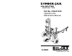
user manual

List of Illustrations
Figure 3-1. Operation Zone.................................................................13
Figure 3-2. Operator Controls.............................................................14
Figure 3-3. Function Interrupt Control Assembly...............................15
Figure 3-4. Wedge Control Assembly ................................................15
Figure 3-5. I-Beam Lock Pin ..............................................................16
Figure 5-1. Replacement Decals .........................................................22
Figure 5-2. Decal Locations................................................................23
Figure 6-1. I-Beam, Cylinder, and Frame Exploded View. ................26
Figure 6-2. Hydraulic Tank and Wheel Exploded View.....................28
Figure 6-3. Hydraulic Pump, Lines, and Valves Exploded View.......30
Figure 6-4. Valve Linkage Exploded View ........................................32
Figure 6-5. Engine and Mounting Hardware Exploded View.............34
Figure 6-6. Hitch and Mounting Hardware Exploded View...............36
List of Tables
Table 2-1. Specifications.....................................................................12
Table 4-1. Daily Service Checks.........................................................19
Table 4-2. Yearly Service Checks.......................................................20
Table 5-1. Replacement Decals...........................................................21
Table 6-1. I-Beam, Cylinder, and Frame Parts List ............................27
Table 6-2. Hydraulic Tank and Wheel Parts List................................29
Table 6-3. Hydraulic Pump, Lines, and Valves Parts List ..................31
Table 6-4. Valve Linkage Parts List ...................................................33
Table 6-5. Engine and Mounting Hardware Parts List........................35
Table 6-6. Hitch and Mounting Hardware Parts List..........................37
ii