INSTRUCTION BOOK OPERATING INSTRUCTIONS MULTI-PURPOSE THRULINE® WATTMETER RF POWER ANALYST® MODEL 4391A ©Copyright 2008 by Bird Electronic Corporation Instruction Book Part Number 920-4391A Rev.
Safety Precautions The following are general safety precautions that are not necessarily related to any specific part or procedure, and do not necessarily appear elsewhere in this publication. These precautions must be thoroughly understood and apply to all phases of operation and maintenance. Keep Away From Live Circuits Operating personnel must at all times observe normal safety regulations. Do not replace components or make adjustments inside the equipment with high voltage turned on.
Bird Model 4391M Power Analyst CAUTION Caution notes call attention to a procedure which, if not correctly performed, could result in damage to the instrument. The caution symbol appears on the equipment indicating there is important information in the instruction manual regarding that particular area. NOTE: Calls attention to supplemental information Fuse Replacement Always use the same type and rating of fuse when replacing the fuse. Fuse information can be found in the parts list on page 30.
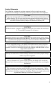
Caution Statements The following equipment cautions appear in the text whenever the equipment is in danger of damage, and are repeated here for emphasis. CAUTION Long-term storage of this instrument can affect battery performance and reduce battery life. Do not store the instrument for long periods of time without recharging the batteries (refer to page 19). Failure to comply may result in reduced battery charge and shortened battery life.
Bird Model 4391M Power Analyst Safety Statements USAGE ANY USE OF THIS INSTRUMENT IN A MANNER NOT SPECIFIED BY THE MANUFACTURER MAY IMPAIR THE INSTRUMENT’S SAFETY PROTECTION. USO EL USO DE ESTE INSTRUMENTO DE MANERA NO ESPECIFICADA POR EL FABRICANTE, PUEDE ANULAR LA PROTECCIÓN DE SEGURIDAD DEL INSTRUMENTO. BENUTZUNG WIRD DAS GERÄT AUF ANDERE WEISE VERWENDET ALS VOM HERSTELLER BESCHRIEBEN, KANN DIE GERÄTESICHERHEIT BEEINTRÄCHTIGT WERDEN.
PRÉVENIR UN CHOC ÉLECTRIQUE DANGEREUX, NE PAS EFFECTUER D’ENTRETIEN SI L’ON N’A PAS ÉTÉ QUALIFIÉ POUR CE FAIRE. UNITS ARE EQUIPPED WITH RECHAREABLE BATTERIES. THESE ARE TO BE REPLACED BY AUTHORIZED SERVICE PERSONNEL ONLY!!! LAS UNIDADES VIENEN EQUIPADAS CON BATERIAS RECARGABLES. ¡¡¡Y SOLAMENTE EL PERSONAL DE SERVICIO AUTORIZADO PUEDE REEMPLAZARLAS!!! GERÄTE SIND MIT WIEDER AUFLADBAREN BATTERIEN BESTÜCKT.
Bird Model 4391M Power Analyst PRIMA DI EROGARE CORRENTE, ASSICURARSI CHE IL SELETTORE DI VOLTAGGIO 115/230 V.C.A. SIA REGOLATO CORRETTAMENTE E CHE IL FUSIBLE ADATTO ALLA LINEA DI ALIMENTAZIONE C.A. SIA INSTALLATO. RF VOLTAGE MAY BE PRESENT IN RF ELEMENT SOCKET KEEP ELEMENT IN SOCKET DURING OPERATION. DE LA TENSION H.F. PEAT ÊTRE PRÉSENTE DANS LA PRISE DE L’ÉLÉMENT H.F. - CONSERVER L’ÉLÉMENT DANS LA PRISE LORS DE L’EMPLOI.
About This Manual This instruction book is arranged so that essential information on safety is contained in the front of the book. Reading the Safety Precautions Section before operating the equipment is strongly advised. The remainder of this manual is divided into Chapters and Sections. Figures and tables are numbered sequentially within each chapter. Chapter Layout Introduction Introduces the external features and and functions of the unit, equipment provided, and optons available.
Bird Model 4391M Power Analyst viii
Table of Contents Safety Precautions . . . . . . . . . . . . . . . . . . . . . . . . . . . . i About This Manual . . . . . . . . . . . . . . . . . . . . . . . . . . vii Introduction . . . . . . . . . . . . . . . . . . . . . . . . . . . . . . . . . 1 Purpose and Function . . . . . . . . . . . . . . . . . . . 1 Description . . . . . . . . . . . . . . . . . . . . . . . . . . . . 2 Theory of Operation . . . . . . . . . . . . . . . . . . . . . . . . . . 3 Description of Operation . . . . . . . . . . . . . . . .
Troubleshooting . . . . . . . . . . . . . . . . . . . . . . . . . . General. . . . . . . . . . . . . . . . . . . . . . . . . . . . . . Disassembly . . . . . . . . . . . . . . . . . . . . . . . . . . . . . Front Panel Removal . . . . . . . . . . . . . . . . . . . Main Printed Circuit (PC) Board Removal . . . QC Connectors Removal . . . . . . . . . . . . . . . . Line Section Removal. . . . . . . . . . . . . . . . . . . Battery Replacement . . . . . . . . . . . . . . . . . . . Parts List . . . . . . . . . . .
Chapter 1 Introduction The Model 4391A is a multi-purpose Radio Frequency wattmeter designed around a microcomputer. A program stored in permanent memory controls the operation of the instrument at all times, permitting the detection and correction of various error sources and the refinement of the raw data produced by the directional detectors.
Bird Model 4391A Power Analyst Description The instrument is housed in an aluminum case approximately 4-3/8 inches high by 9-5/8 inches deep by 6-1/ 4 inches wide (111 mm x 244 mm x 159 mm) including connections, see Figure 1. At each end of the line section are Bird Quick-Change type RF connectors which may be easily interchanged with any other Bird QC connector. See Bird Catalog for types available.
Chapter 2 Description of Operation Theory of Operation Figure 2 is a block diagram of the major functional parts of the Model 4391A RF Wattmeter. The Microcomputer integrated circuit shown, controls all the other portions of the instrument, which fall into two major groups. Figure 2 Circuit Block Diagram Keyboard, Range Switches, and Display Group The keyboard and range switches serve only to pass information to the computer.
Bird Model 4391A Power Analyst Each reading output by the display is derived from up to three voltage readings using the circuitry described above. Once these voltages are measured, all remaining operations are performed within the computer chip as follows: The voltages are corrected for error due to dc drift in the analog circuitry. Each voltage is converted to square root of power using stored data tables. These values are then combined mathematically to arrive at the final result in binary.
Theory of Operation The electrical values of the element circuits are carefully balanced and designed so that current from the reverse wave will cancel the other almost completely. The result is directivity always higher than 25 dB, which means that the element is highly insensitive (nulled) to the REVERSE direction wave. Being highly directional, the Thruline element is sensitive (at one setting) only to one of the travelling waves that produce standing waves by interference.
Bird Model 4391A Power Analyst 6
Chapter 3 Installation The Model 4391A RF Power Analyst is completely portable and very suitable for field or laboratory use. Its power is derived from rechargeable nickel metal hydride batteries inside the unit or from an AC outlet via the power cord supplied with the device. The batteries are shipped in a low charge state. It is, therefore, recommended that you charge the instrument for 16 hours before using it for continuous operation.
Bird Model 4391A Power Analyst Connections The Model 4391A contains a short section of rigid 50 ohm coaxial air dielectric transmission line. To make measurements relating to the travelling waves in a coaxial line, that line must be disconnected at some convenient point to permit the Model 4391A air line to be inserted. Although the Model 4391A is normally supplied with two Female N-type connectors, a variety of easily interchangeable connectors are available to facilitate connecting to the user’s system.
Installation with the nominal power range of the elements. For example, if the forward element is a 5 watt element, the switches are set at 5 and x1. For a 250 watt element they are set at 2.5 and x100. Sometimes it is necessary to use milliwatts or kilowatts as the unit of measure. In other words, 1 watt becomes 10 x 100 milliwatts and 2500 watts becomes 2.5 x 1 kilowatts.
Bird Model 4391A Power Analyst 10
Chapter 4 Operating Modes Reading Forward CW Power Operating Instructions The Model 4391A has nine modes of operation which are selected by pressing the mode keys momentarily. In addition, each mode has three output options selected by pressing the modifier keys. Detailed descriptions of the modes and output options follow. For this measurement only a forward element is needed.
Bird Model 4391A Power Analyst signal coming from the element, whereas the Model 4391A uses peak and negative peak detector circuits to measure peak and minimum square root of power and combines them using the equation: Peak Power + Minimum Power 2 CW POWER = ⎛⎝ ------------------------------------------------------------------------------------⎞⎠ 2 With this technique, operation of CW mode is predictable regardless of envelope shape (see Figure 4).
Operating Instructions Table 2 Voltage Standing Wave Ratio (VSWR) Measuring Peak Envelope Power VSWR Return Loss (dB) Reflected Power % 1.01 46.1 0.00 1.02 40.1 0.01 1.03 36.6 1.04 VSWR Return Loss (dB) Reflected Power % 1.45 14.7 3.37 1.50 14.0 4.00 0.02 1.75 11.3 7.44 34.2 0.04 2.00 9.50 11.11 1.05 32.3 0.06 2.25 8.30 14.79 1.06 30.7 0.08 2.50 7.40 18.37 1.07 29.4 0.11 2.75 6.60 21.78 1.08 28.3 0.15 3.00 6.00 25.00 1.09 27.3 0.19 3.25 5.50 28.
Bird Model 4391A Power Analyst Measuring Amplitude Modulation Only a forward element is required for this mode. Point the element in the direction of forward power and press % MOD. Modulation is displayed directly in percent, provided the average signal is above 10% and the PEP of the signal is below 400% of the element’s nominal full scale. For specified accuracy, the average CW power levels must be greater than one-third of full scale.
Operating Instructions Measuring Power in dBm Operation of the forward and reflected dBm modes is identical to the forward and reflected CW power modes, except that the resulting reading is converted to dB above 1 milliwatt before it is displayed. It should be noted that in doing this conversion, the range set on the slide switches is assumed to be watts rather than kilowatts or milliwatts. If it is not, 30.
Bird Model 4391A Power Analyst Insertion Loss or Attenuation Table 5 Correction Factors Monitoring Maximum and Minimum Readings 16 Attenuation or insertion loss can be measured directly using an external single port line section (P/N 4230-006-1), a dc feed-in adapter (P/N 4381-050), and a dc cable (P/N 3170058-6). The Model 4391A is inserted at the source end of the device being measured.
Operating Instructions Figure 13 Maximum or Minimum Readings Using the Peaking Aid The peaking aid is useful for making adjustments to optimize any of the parameters which the Model 4391A measures. After the mode is selected, press the delta (∆) key momentarily. This blanks the least significant digit of the display, and replaces it with a right-facing arrow head if the measured quantity is increasing or a left-facing arrow head if it is decreasing. If there is no change, the digit is left blank.
Bird Model 4391A Power Analyst Battery Care With average use, the nickel metal hydride batteries in the 4391A will power the unit for 12 hours before needing recharged. The 4391A will maintain rated accuracy until all the decimal points light, indicating that recharging is required. To recharge, connect AC power to the unit. To fully charge the batteries requires approximately 16 hours.
Chapter 5 Maintenance The 4391A RF Power Analyst was designed and built to provide many years of trouble free service. This section provides the information needed to prevent and correct equipment failure. Preventive Maintenance To avoid unnecessary damage, always observe the following cautions: 1. 2. 3. Cleaning and Inspection The RF Power Analyst is a rugged and portable instrument intended for field use. However, it should not be unnecessarily exposed to extreme environmental conditions.
Bird Model 4391A Power Analyst then perform a full charge again. If necessary, repeat this discharge and charge cycle up to three times. If the batteries do not remain charged after three discharge-charge cycles, replace the batteries. WARNING Use only NIckel Metal Hydride (NiMH) batteries that have a minimum capacity of 4600 milliamper hours (mAh). Do not install batteries that are not Nickel Metal Hydride. Do not install NiMH batteries that have less than 4600 mAh capacity.
Maintenance 5. 6. 7. Switch on the Calibrator/Source and let it warm up for at least one hour. Set the Calibrator/Source to output 30 ±0.05 microamps. Adjust potentiometer, R25 (Figure 15, page 21), until the RF Power Analyst Displays 1000 ±5. Figure 15 Calibration Potentiometer Element Wiper Contact Adjustment CAUTION If the element cannot be fully inserted into the socket, do not force it. You might damage the element.
Bird Model 4391A Power Analyst Perform the following steps to adjust the contact spring. 1. Using a small flat head screwdriver, place the flat side of the screwdriver behind the contact bar as indicated and bend the contact bar so that the contact rests in the center of the slot adjacent to the element socket (Figure 16). Figure 16 Adjust Element Contact Up and Down 2.
Maintenance Troubleshooting General The troubleshooting instructions are intended to aid in fault isolation. This is accomplished through the use of a troubleshooting table. First, locate the symptom(s) in the problem column of Table 8. In some cases the same fault can have more than one symptom and more than one possible remedy. Compare the possible causes until you arrive at a suspected fault. Once a fault has been isolated, repair or replace the defective components.
Bird Model 4391A Power Analyst PROBLEM Display indicates “0” Power POSSIBLE CAUSE Element wiper not contacting the element Defective Plug-in Element Defect on Data Acquisition PC board assembly One segment of a display doesn’t light All decimal points stay lit Defective Display Low charge on the batteries Defective circuit component Defective circuit component Same segment on all displays doesn’t light One or more keys do not function REMEDY Readjust the element wiper to make good contact (page 21).
Maintenance 5. 6. Lift the front panel from the housing. Be careful to clear the line section blocks. Remove pads from the three toggle switches. Figure 18 Removing Front Panel Main Printed Circuit (PC) Board Removal 1. 2. 3. Remove the front panel (Refer to “Front Panel Removal” on page 24) Disconnect cable assembly at header (P1) (Figure 19, page 26, item 1). Remove the six screws and washers that secure the circuit board supports to the housing (item 2). CAUTION Internal batteries are connected.
Bird Model 4391A Power Analyst Figure 19 Removing Main PCB QC Connectors Removal 26 1. 2. Remove the eight screws (four on each connector) that secure the connectors to the housing (Figure 20, item 1). Remove the two “QC” connectors (item 2) by pulling them away from the line section assembly.
Maintenance Line Section Removal 1. 2. 3. Remove the QC connectors (page 26). Remove the four screws and lock washers that secure line section assembly to the housing (item 3). Using minimum pressure, spread apart the sides of the lower housing assembly just far enough to allow the line section assembly to be removed. Figure 20 Removing QC Connectors and Line Section To remove the line section PCB, continue with the next steps. CAUTION This instrument contains static sensitive electronic components.
Bird Model 4391A Power Analyst 6. 7. Remove the two screws (item 4) that secure the PCB to the line section then pull the PC board assembly (item 3) away from the line section subassembly. Remove the spacers (item 2). Remove keying beads (item 1) from the element wiper contacts on the PC board assembly. Figure 21 Removing Line Section PCB Battery Replacement 1. 2. 3. 4. 5. 6. 7.
Maintenance 8. Lower and secure the Main PC board assembly 9. Replace and secure the front cover. 10. Charge the batteries for 16 hours before using the instrument.
Bird Model 4391A Power Analyst Parts List This section contains an illustrated list of all authorized replacement parts for the 4391A RF power Analyst. Parts are grouped into major assemblies and subassemblies. Figure 24 Parts Drawing Item No. Description Part No.
Maintenance Figure 25 Line Section Assembly (S/N 1723 and below) Item No. Description Part No. Qty Figure 25 1 Line Section, Subassembly 4381-005 2 PC Board, Data Acquisition Assy 4391A006 1 1 3 Bead, Keying 4391-026 2 4 Spacer 4391-027 2 5 Screw, Machine, filister head, No. 4-40, 1/4 in. lg, sst COML 2 6 Support 4381-029 2 7 Screw, Machine, filister head, No. 8-32, 1/2 in. lg, sst COML 4 8 Screw, Machine, filister head, No. 4-40, 7/8 in.
Bird Model 4391A Power Analyst Figure 26 Line Section Assembly (S/N 1724 and above) Part No. Description Part No. Qty Figure 26 32 1 Line Section, Subassembly 4381-005 2 PC Board, Data Acquisition Assy 4391A006 1 1 3 Bead, Keying 4391-026 2 4 Spacer 4391-027 2 5 Screw, Machine, filister head, No. 4-40, 1/4 in. lg, sst COML 2 6 Support 4381-029 2 7 Screw, Machine, filister head, No. 8-32, 1/2 in. lg, sst COML 4 8 Hex Nut, with nylon insert, No.
Maintenance Customer Service Any maintenance or service procedure beyond the scope of those in this chapter should be referred to a qualified service center. If you need to return the unit for any reason, contact the Bird Service Center for a return authorization. All instruments returned must be shipped prepaid and to the attention of Bird Service Center. Bird Service Center 30303 Aurora Road Cleveland (Solon), Ohio 44139-2794 Phone: (440) 519-2298 Fax: (440) 519-2326 E-mail: bsc@bird-technologies.
Bird Model 4391A Power Analyst Specifications Measuring Medium RF Power Range* Usable Over-Range* RF Transmission in 50 ohm lines 100 mW to 10 kW full scale using Bird Plug-in Elements. Accuracy not guaranteed with components not supplied by Bird To 120% of scale on CW, PEP, SWR, and Return loss functions. To 400% of scale (PEP) on dBm and 0% modulation. 450 kHz to 2.
Limited Warranty All products manufactured by Seller are warranted to be free from defects in material and workmanship for a period of one (1) year, unless otherwise specified, from date of shipment and to conform to applicable specifications, drawings, blueprints and/or samples.