User Manual MDS932AE-10BT STANDALONE MDS932AE-FXO STANDALONE MDS932AE-FXS STANDALONE MDS933AE-10BT STANDALONE MDS932C-10BT RACK-CARD MDS933C-10BT RACK-CARD G.SHDSL Modem USER MANUAL Version 1.2 Revision 26 January 2004 Document name MDS933AE-v1.2.
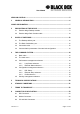
User Manual VERSION CONTROL.......................................................................................................... 5 1 GENERAL INFORMATION........................................................................................ 6 ORDER INFORMATION ..................................................................................................... 7 2 3 4 DESCRIPTION OF THE DEVICE .............................................................................. 8 2.
User Manual 8.4 9 Line1 and Line2 Connector ............................................................................. 24 DESCRIPTION OF INTERFACE CABLES.............................................................. 25 9.1 Ethernet cable ................................................................................................. 25 9.2 DSL cable........................................................................................................ 25 Version: 1.2 Page.
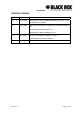
User Manual VERSION CONTROL Version Date Major changes to previous version 1.0 31.12.2001 Initial version of the manual corresponding to version 1.2 of the device micro program 1.1 23.10.2003 New function description corresponding to software release V1.6 Corrected Connecter description 9.1 Changed DSL cable to twisted type 10.2 1.2 26.1.2004 Manual corresponding to software version 1.7 Implementation of rack card models Version: 1.2 Page.
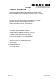
User Manual 1 GENERAL INFORMATION • High-speed symmetrical data transmission over one physical copper twisted pair with the 135 Ohm impedance according to ETSI TS 101 135. • ITU-T G.991.2 (G.shdsl) line encoding. • Line rate in the range from 72 Kbit/s to 2320 Kbit/s in 2 wire mode Line rate in the range from 144 Kbit/s to 4624 Kbit/s in 4 wire mode • Manual or automatic mode of line-speed adjustment. • Ethernet 10/100Base-T interface, Full/Half duplex. • Transmition of VLAN packet (IEEE-802.
User Manual ORDER INFORMATION MDS932AE-10BT Modem AccessDSL Discovery, G.shdsl, 10/100Base-T Bridge, VLAN, Adapter 220 Vac MDS933AE-10BT Modem AccessDSL Discovery, G.shdsl, 1 or 2 pairs, up to 4.6Mbps, 10/100Base-T Bridge, VLAN, Adapter 220 Vac MDS932AE-FXS Modem AccessDSL Discovery, G.shdsl, 10/100Base-T Bridge, VLAN, Adapter 220 Vac, with FXS interfaces MDS932AE-FXO Modem AccessDSL Discovery, G.shdsl, 10/100Base-T Bridge, VLAN, Adapter 220 Vac, with FXO interfaces Version: 1.2 Page.
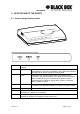
User Manual 2 DESCRIPTION OF THE DEVICE 2.1 Exterior design Desktop models The front panel of the device has 3 LEDs: LOCAL informs the user about the status of the local device. The following four statuses are possible «blinking red» informs the user about malfunctioning of the modem’s hardware and software. In this case, the modem is out of order and should be submitted to the service center for being repaired. «red» informs the user about an urgent alarm.
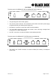
User Manual The back panel of the MDS932AE-10BT and MDS933AE-10BT modem has: • The grounding bolt of the modem (option); • The “AC12V” power connector.
User Manual 2.
User Manual Status(L) informs the user about the status of the local device. The following four statuses are possible «blinking red» informs the user about malfunctioning of the modem’s hardware and software. In this case, the modem is out of order and should be submitted to the service center for being repaired. «red» informs the user about an urgent alarm.
User Manual 3 RULES OF SWITCHING 3.1 The standalone delivery set The delivery set includes: • the subscriber access device (a modem) • the power supply source (an AC adapter) • the cables for the line connections 3.2 The rack-card delivery set The delivery set includes: • the subscriber access device (a modul) • the cables for the line connections 3.
User Manual To update the information on the screen use the “Enter” key. The following menu will appear on the screen. Input Password: Please enter your programmed password. The unit will be delivered with the default password “admin” After entering the password the following menu will appear. Discovery G.SHDSL Ethernet Monitor V1.7 +-----------------------+ + Main Menu + +-----------------------+ 1. Performance management (PM) 3. Configuration management (CM) 4. Security management (SM) 5.
User Manual 4 THE COMMAND SYSTEM 4.1 Basic rules After the command is typed, press . The key is used to edit commands. It is necessary to input item number, for choising menu item, You can use “PageUP”, “PageDown” and “Space” keys, for scrolling list of available value of parameters, The “Esc” key is using for channeling of new value of parameters or returning to up menu screen. 4.2 The main menu The main menu is the following: Discovery G.SHDSL Ethernet Monitor V1.
User Manual 4.3 Performance management submenu Upon activation of the performance management submenu the following message will be displayed. Performance Management 1.Loop Status... 4.EtherNet Status... Select item number or ESC to Upper level menu>> 4.3.1 Loop Status submenu Upon activation of the performance management submenu the following message will be displayed.
User Manual 4.3.2 Ethernet Status submenu Upon activation of the performance management submenu the following message will be displayed. Performance Management->EtherNet Status Link:Link down Used Entries:0 Fwd Packets:0 Speed:Auto Link Speed:---Tx Packets:0 Drop Packets:0 Duplex:Auto Link Duplex:---Rx Packets:0 MAC Address:00-00-00-00-00-00 1.Clear Counters Select item number or ESC to Upper level menu>> 4.
User Manual 4.4.1 DSL Setup In this menu you can setup the DSL link. When you have selected that menu, the following will appear: Configuration Management->DSL Setup 1.[Loop 1 Operation Mode]:Slave 2.[Loop 1 Auto/Fixed]:Fixed 5.[Loop 1 Fixed Connection Speed]:2312K(36N) 6.[Loop 1 Annex]:A/B 7.[Loop 1 Tx Level Adjustment]:0 dB 18.[2W/4W]:2W Select item number or ESC to Upper level menu>> 4.4.1.1 Operation Mode In this menu you can setup the unit to one of the following states: Master, Slave 4.4.1.
User Manual 4.4.1.4 Fixed Connection Speed (only if Fixed is selected) • In the Fixed Connection Speed menu, you can specify your desired speed in the range of 72 kbps to 2312 kbps for 2wire units and 144 kbps to 4624 kbps for 4wire models 4.4.1.5 Annex • With the Appendix menu you can choose between A, B, A / B. If you don’t know what Annex you have to setup, and then use the A / B configuration. 4.4.1.
User Manual 4.4.2 Ethernet Setup submenu Configuration Management->EtherNet Setup 1.[Speed]:Auto 2.[Duplex Mode]:Auto 3.[Disable Mac Filter]:No 4.IP Address>>192.168.5.105 5.Subnet Mask>>255.255.255.0 6.Gateway Address>>192.168.5.
User Manual 5 TECHNICAL SPECIFICATIONS The main technical specifications of modems of the Black Box family are presented below in the table. Line interface. Standard ETSI 101 135 Number of pairs 1 Line rate 2 wire models 72 – 2312 Kbit/s 4 wire models 144 – 4624 Kbit/s Communication range for cables with the wire diameter of 0.4 mm: 0.9 mm: approx: aprox: 144 Kbit/s 8.2 km 31 km 2320 Kbit/s 3.6 km 13.7 km (values are depending on noise environment and line quality) Line code G.
User Manual 6 STORAGE CONDITIONS The equipment of the Black Box family while being packed should withstand all means of transport at a temperature in the range form -50о С to +50о С and the relative humidity of air up to 100% at 25о С. The equipment can also withstand air-transport at a low air pressure of 12 kPa (90 Torr) at -50о С.
User Manual 7 TERMS TO TRANSPORT The equipment of the Black Box family should be packed and transported by: • motor transport with an enclosed truck body; • enclosed railroad cars; • unpressurized airplanes and helicopters (up to 10000 m at an air pressure of 170 Torr); • river transport (in holds).
User Manual 8 CONNECTOR’S DESCRIPTION 8.1 DSL Connector Type: RJ-45, 8 pin 1 8.2 8 RJ-45 Number Signal Assignment 1,2 NC - 3 LB,a Ttp (4W model only) 4 LA,a tip 5 LA,b ring 6 LB,b ring (4W model only) 7,8 NC - Monitor Connector Type: Sub-D9, female 1 6 DB9 9 5 female Version: 1.2 Number Signal Assignment 1 NC - 2 TXD Transmit data 3 RXD Receive data 4 DTR Data terminal ready 5 SGND Signal ground 6 NC - 7 NC - 8 NC - 9 NC - Page.
User Manual 8.3 PC and Hub Connectors Type: RJ-45 1 8.4 8 RJ-45 Number PC assignment HUB assignment 1 Tx+ Rx+ 2 Tx- Rx- 3 Rx+ Tx+ 4 NC NC 5 NC NC 6 Rx- Tx- 7 NC NC 8 NC NC Line1 and Line2 Connector Type: RJ-11, 4 pin 1 Version: 1.2 4 RJ-11 Number Signal Assignment 1 NC - 2 LA,a tip 3 LA,b ring 4 NC - Page.
User Manual 9 DESCRIPTION OF INTERFACE CABLES 9.1 Ethernet cable Side А Color of wire Side B 1 white/green 1 2 green/white 2 3 white/orange 3 4 blue/white 4 5 white/blue 5 6 orange/white 6 7 white/brown. 7 8 brown/white 8 Side А Color of wire Side B 1 white/green 1 2 green/white 2 3 white/orange 3 4 blue/white 4 5 white/blue 5 6 orange/white 6 7 white/brown. 7 8 brown/white 8 9.2 DSL cable Version: 1.2 Page.