APRIL 2001 5 6 7 1 2 3 13 14 15 9 10 11 5 6 7 1 2 3 8 User A User B 4 select power 16 12 8 User A User B 4 select power Customer Support Information: FREE tech support 24 hours a day, 7 days a week: Call 724-746-5500 or fax 724-746-0746. Mailing address: Black Box Corporation, 1000 Park Dr., Lawrence, PA 15055-1018 World-Wide Web: www.blackbox.com • E-mail: info@blackbox.com © Copyright 2001. Black Box Corporation. All rights reserved.
THE SERVSWITCH™ FAMILY Welcome to the ServSwitchTM Family! Thank you for purchasing a BLACK BOX® ServSwitch™ Brand KVM switch! We appreciate your business, and we think you’ll appreciate the many ways that your new ServSwitch keyboard/video/mouse switch will save you money, time, and effort. That’s because our ServSwitch family is all about breaking away from the traditional, expensive model of computer management.
MATRIX SERVSWITCH™ TRADEMARKS USED IN THIS MANUAL BLACK BOX and the logo are registered trademarks, and ServSwitch, ServSwitch Ultra, and Matrix ServSwitch are trademarks, of Black Box Corporation. Apple, Mac, and Macintosh are registered trademarks of Apple Computer, Inc. Compaq and Alpha are registered trademarks, and DEC is a trademark, of Compaq Computer Corporation. HP is a registered trademark of Hewlett-Packard.
FCC/IC STATEMENTS, EU DECLARATION OF CONFORMITY FEDERAL COMMUNICATIONS COMMISSION AND INDUSTRY CANADA RADIO-FREQUENCY INTERFERENCE STATEMENTS This equipment generates, uses, and can radiate radio frequency energy and if not installed and used properly, that is, in strict accordance with the manufacturer’s instructions, may cause interference to radio communication.
MATRIX SERVSWITCH™ NORMAS OFICIALES MEXICANAS (NOM) ELECTRICAL SAFETY STATEMENT INSTRUCCIONES DE SEGURIDAD 1. Todas las instrucciones de seguridad y operación deberán ser leídas antes de que el aparato eléctrico sea operado. 2. Las instrucciones de seguridad y operación deberán ser guardadas para referencia futura. 3. Todas las advertencias en el aparato eléctrico y en sus instrucciones de operación deben ser respetadas. 4. Todas las instrucciones de operación y uso deben ser seguidas. 5.
NOM STATEMENT 12. Precaución debe ser tomada de tal manera que la tierra fisica y la polarización del equipo no sea eliminada. 13. Los cables de la fuente de poder deben ser guiados de tal manera que no sean pisados ni pellizcados por objetos colocados sobre o contra ellos, poniendo particular atención a los contactos y receptáculos donde salen del aparato. 14. El equipo eléctrico debe ser limpiado únicamente de acuerdo a las recomendaciones del fabricante. 15.
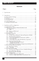
MATRIX SERVSWITCH™ Contents Chapter Page 1. Specifications ........................................................................................... 10 2. Introduction ............................................................................................. 2.1 The Complete Package ..................................................................... 2.2 Features ............................................................................................. 2.3 The Front Panel .....................
TABLE OF CONTENTS Chapter Page 4. Full Configuration ................................................................................... 4.1 Using the Menu ................................................................................ 4.1.1 Navigating the Configuration Pages .................................... 4.1.2 Choosing Names ................................................................... 4.1.3 Saving Configuration Changes ............................................. 4.
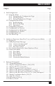
MATRIX SERVSWITCH™ Contents (continued) Chapter 6. 7. 8. Page Keyboard Commands (continued) 6.12 Reset/Enable Mouse in Windows NT and UNIX: [Ctrl] O ......................................................................................... 6.13 Send Null Byte to PS/2 Type Mouse: [Ctrl] N .............................. 6.14 Identify Firmware Revision: [Ctrl] I ............................................... 6.15 Start Scan: [Ctrl] S .........................................................................
TABLE OF CONTENTS Appendix Page Appendix E: Installing Modules in the Matrix ServSwitch ......................... E.1 Setting the RING/BUS Jumper (Jumper JP1) on Expansion Modules ................................................................ E.2 Swapping In an Expansion Module ............................................... E.3 Swapping In a Terminator Module (Not Recommended) .......... 106 106 107 108 Appendix F: Rackmounting the Matrix ServSwitch ....................................
MATRIX SERVSWITCH™ 1. Specifications Hardware Required — Monitor that supports your computers’ highest video standard; in multiplatform applications, should be a multisync model capable of forming video from either composite sync or separate horizontal and vertical sync signals (see Section 3.2.
CHAPTER 1: Specifications Maximum Distance — 20 ft. (6.1 m) of CPU or User Cable—possibly as much as 100 ft. (30.5 m) of coaxial CPU or User Cable, depending on CPUs, monitor, and video resolution (see Section 3.2.3)—from any Matrix ServSwitch to any device attached to it; 100 ft. (30.5 m) of Expansion Cable between any two Matrix ServSwitches; 50 ft. (15.
MATRIX SERVSWITCH™ Maximum Altitude— 10,000 ft. (3048 m) Temperature Tolerance— 32 to 113˚F (0 to 45˚C) Humidity Tolerance— 5 to 80% noncondensing Enclosure — Steel Power — From AC outlet through included power cord and power inlet to internal transformer: SW7x1A-R3, SW7x2A-R3: 85 to 250 VAC, 47 to 63 Hz; SW7x3A-R3: 90 to 264 VAC, 47 to 63 Hz; Consumption: SW7x1A-R3, SW7x2A-R3: Up to 20 VA (20 watts); SW7x3A-R3: Up to 45 VA (45 watts) Size — SW7x1A-R3, SW7x2A-R3: 1.75"H (1U) x 16.8"W x 4.8"D (4.
CHAPTER 2: Introduction 2. Introduction Thank you for choosing a Matrix ServSwitch™. Designed with your needs in mind, your new Switch will simplify your job by helping you organize your multiplecomputer application. With your Switch you can use two keyboards, monitors, and mice to access a number of IBM® PC compatible computers, so you can significantly reduce your equipment overhead and end keyboard and monitor clutter.
MATRIX SERVSWITCH™ 2.2 Features With the Matrix ServSwitch, you have easy, virtually trouble-free, secure, and complete access to up to 1000 computers from as many as four keyboard/video/ mouse stations. Here are some of the major features of the Switch: Upgradability: • The plug-in Expansion Module gives your Matrix ServSwitch system room to grow. • Free lifetime firmware upgrades using flash-memory technology mean you’ll always have the latest improvements and new features.
CHAPTER 2: Introduction Flexibility: • Full-featured command set includes a scan command to automatically switch through a subset of computers over the course of an adjustable time interval. • You can use keyboard commands, on-screen menus, or RS-232 devices to switch computers to your keyboard/video/mouse station. • Integrated autoswitching power supply can be connected to either 110-VAC or 220-VAC outlets.
MATRIX SERVSWITCH™ 2.3 The Front Panel The Switch’s front panel features two pushbutton switches and several LED indicators. To familiarize yourself with these controls and indicators, refer to Figure 2-1 and the descriptions that follow on the next page. Power 13 14 15 16 9 10 11 12 5 6 7 8 1 2 3 4 Figure 2-1. The front panel of a 2 x 16 Matrix ServSwitch (SW743A-R3).
CHAPTER 2: Introduction Panel Label Description POWER (left) Main Power LED: Lights to indicate that the Matrix ServSwitch is powered ON. [Numbered] CPU Status LEDs: Numbered pairs of LEDs indicate the status of the CPU connected to the corresponding port on the rear panel: Left/Red (Select) Lights if the corresponding port is currently selected by either station. Right/Green (CPU Power) Lights if the device on the corresponding port is powered ON.
MATRIX SERVSWITCH™ 2.4 The Rear Panel All cable connections are made at the Switch’s rear panel, as illustrated in Figures 2-2 and 2-3 and described below and on the next page. Figure 2-2. The rear panel of a 2 x 16 Matrix ServSwitch with an Expansion Module installed. Figure 2-3. The same rear panel, board and port numbering shown. Designation Connector Description IN DB15 F On Expansion Module: Carries keyboard/mouse/ video data input from other Matrix ServSwitches to the local Switch.
CHAPTER 2: Introduction Designation Connector Description N [CPU N] DB25 F Connect the sharing computers to these ports with CPU Cables. At the Matrix ServSwitch end, these cables have a DB25 male connector; at the other ends, they have appropriate connectors to plug into your CPUs’ video, keyboard, and mouse ports. These cables take the signals that would normally pass between the CPUs’ ports and the monitor, keyboard, and mouse, and carry them between the CPUs’ ports and the Switch instead.
MATRIX SERVSWITCH™ 2.5 Cable Requirements Many switches of this type have what seems like ten million connectors on their rear panels: one for each CPU’s video cable, one for each keyboard cable, and a third for each mouse cable. The potential for tangling or mismatching cables is high. By contrast, you can connect the Matrix ServSwitch to your CPUs with one CPU Cable (also called a “CPU Adapter Cable”) for each CPU. This single cable reaches the CPU’s video-output, keyboard, and mouse ports.
CHAPTER 3: Installation and Preconfiguration 3. Installation and Preconfiguration 3.1 Quick Setup Guide Figure 3-1 shows a basic example of taking a Matrix ServSwitch and connecting it to a CPU, a user station (monitor, keyboard, and mouse), another Switch, and AC power. IBM PC equipment is shown, but the principles will be similar for all equipment types. Connectors will vary depending on the types of equipment you are installing.
MATRIX SERVSWITCH™ 3.2 Guidelines for Using the Matrix ServSwitch with Your Equipment 3.2.1 CPUS If you will be attaching IBM PC type computers, use only IBM PC/AT, PS/2, RS/6000®, or 100% compatible machines, or recent SGI® machines. The Matrix ServSwitch does not support IBM PC/XT™ or compatible machines. It also does not support machines that output CGA or EGA video.
CHAPTER 3: Installation and Preconfiguration particular, use Windows keyboards if any of your applications require the Windows keys, and use three-button mice if any of your applications require the center mouse button. Other concerns: • The Matrix ServSwitch emulates several types of mice for the attached computers, but the actual mice used at your user stations must be the same type as the stations’ keyboards: Sun mice with Sun keyboards or PS/2 mice (not serial mice) with PC type keyboards.
MATRIX SERVSWITCH™ • The Matrix ServSwitch is designed to support IBM PC compatible 101-, 102-, 104-, or 105-key keyboards and IBM PC keyboard-scan modes 1, 2, and 3; it’s also designed to work with PC-type CPUs/keyboards that use 5-pin DIN or 6-pin mini-DIN keyboard connectors.
CHAPTER 3: Installation and Preconfiguration Table 3-1. Keyboard mapping by the Matrix ServSwitch. Generally, the Matrix ServSwitch interprets keys by their positions on the keyboard, so any keys that occupy more or less the same positions and perform more or less the same functions across platforms will map one-to-one. However, certain keys available on certain keyboards do not correspond well or are not available on other types of keyboards, so the Switch maps the more important of these as shown below.
MATRIX SERVSWITCH™ 3.2.3 MONITOR If all of your CPUs are of the same type, we recommend that you use the corresponding type of monitor. If your CPUs are of different types, the monitor must be a multisync model, able to sync to every CPU’s video-output frequencies, and compatible with all of the CPUs’ video cards.
CHAPTER 3: Installation and Preconfiguration The Matrix ServSwitch will support SVGA (Super VGA) video, but with original Serv cables the video quality can decrease at higher resolutions and distances. Table 3-2 illustrates this. The distances in the table are total lengths of CPU Cable and User Cable (but not Expansion Cable) measured from the CPU to the monitor.
MATRIX SERVSWITCH™ By contrast, coaxial cables (standard for Sun applications, required for XGA applications, and recommended for most other applications) do much better at maintaining video quality, as shown in Table 3-3. (For the meaning of quality numbers 3, 2, and 1, see the bottom of the previous page.) As before, the distances in the table are total adapter-cable lengths (not including Expansion Cable) measured from the CPU to the monitor.
CHAPTER 3: Installation and Preconfiguration 3.3 Installation Procedure This section provides complete instructions for the hardware setup of a single Matrix ServSwitch. (For detailed instructions on installing a daisychained Matrix ServSwitch system, see Sections 3.3.6 and 3.4.) For an illustrated example of the elements of a basic setup, see Figure 3-1. For the procedure you should use to power up the system, see Section 3.5. For the initial configuration procedure, see Section 3.6.
MATRIX SERVSWITCH™ 3.3.3 RACKMOUNTING (OPTIONAL) If you want to mount the Matrix ServSwitch in a rack, you will need a ServSwitch Rackmounting Kit. Our product code for a 19", 23", or 24" Kit that fits the 2 x 4 and 2 x 8 Matrix ServSwitches is RMK19B, RMK23B, or RMK24B respectively. Our product code for a 19", 23", or 24" Kit that fits the 2 x 16 Matrix ServSwitch is RMK19C, RMK23C, or RMK24C respectively. See Appendix F for more information. 3.3.
CHAPTER 3: Installation and Preconfiguration 3.3.5 CONNECTING CPUS CPU Cables run from the Matrix ServSwitch to the keyboard port, mouse port (if this is separate), and video-output port of each CPU you want to directly attach to it. Different types of this cable fit the connectors on different computers (see Appendix B). This cable also comes in the different lengths supported by different applications (see Section 3.2.3). 1. Make sure that the Matrix ServSwitch is turned off and unplugged. 2.
MATRIX SERVSWITCH™ 6. Plug each (remaining) CPU Cable’s video-, keyboard-, and (on IBM type cables) mouse-port connectors into the corresponding ports on each CPU (or into the Video Adapter on a non-VGA Mac). For various reasons, the CPU should be OFF when you do this. (The Switch also needs to be configured before you turn ON the CPUs; see Section 3.6.) Avoid plugging CPUs into the Switch if they are already ON; if you accidentally do so with an IBM type CPU, see Section 4.
CHAPTER 3: Installation and Preconfiguration 3.3.7 POWERING UP THE SWITCHES 1. Making sure that the connected CPUs are OFF (powered down)—except for at least one CPU in an all Sun installation where the monitor doesn’t support 640 x 480 (see step 5 in Section 3.3.5)—take the power cord of a Matrix ServSwitch in your system and plug the cord’s IEC 320 female outlet end into the Switch’s rear-mounted IEC 320 male power inlet. Then plug the other end of the cord into a working outlet.
MATRIX SERVSWITCH™ 3.3.9 SWITCHING AND ACCESSING THE DISPLAY FROM THE KEYBOARD If your Matrix ServSwitch system has been properly preconfigured (see Section 3.6), it is now ready for operation using its default settings. To take full advantage of the Switch’s keyboard-command features, refer to Chapter 6, which gives detailed information about each of the Switch commands, describing each command’s function and keystroke sequence. For your convenience, this information is summarized in Section 6.1.
CHAPTER 3: Installation and Preconfiguration 3.4 Daisychaining Matrix ServSwitches Chaining multiple Matrix ServSwitches together adds capacity for more computers and, optionally, more user stations. When you plan a daisychained system, keep in mind that Switches attach to each other: • From output to input. • In a bus or ring topology. • With one or two cables. Each Switch must have its “starting computer” configuration parameter set correctly before you attach it to other Switches. See Section 3.
MATRIX SERVSWITCH™ 3.4.2 TOPOLOGIES IMPORTANT NOTE A standard Matrix ServSwitch system can support two independent users, but each of the user stations has to be attached to a differentnumbered KVM port (one to KVM 1, the other to KVM 2), even if the stations are attached to different Switches. If you have users on stations attached to same-numbered ports (both on KVM 1, for instance), the users will share a video bus. Refer to Section 5.3.
CHAPTER 3: Installation and Preconfiguration Unit 3: CPUs 33 to 48 Cable runs from OUT on Unit 1 to IN on Unit 3 User B (KVM 2) Cable runs from OUT on Unit 3 to IN on Unit 2 Unit 2: CPUs 17 to 32 Cable runs from OUT on Unit 3 to IN on Unit 2 Unit 1: CPUs 1 to 16 User A (KVM 1) Figure 3-4. The ring topology. Use a ring arrangement if you have user stations attached to two different Matrix ServSwitches and you want both of the users to have access (or at least potential access) to all CPUs.
MATRIX SERVSWITCH™ 3.5 The Power-Up Procedure About three seconds after you plug in and turn on a Matrix ServSwitch as described in Section 3.3.7, a diagnostics screen running a self-test will appear on user-station monitors and serial devices attached to the Switch.
CHAPTER 3: Installation and Preconfiguration 3.5.1 THE POWER-UP DIAGNOSTIC SCREEN: STANDARD MESSAGES The diagnostic screen that appears when you turn ON the Matrix ServSwitch is shown in Figure 3-5; standard messages you might see on it are shown in Table 3-4 on the next page.
MATRIX SERVSWITCH™ Table 3-4. The standard diagnostic-screen messages. Diagnostic Messages Description Kernel Version Indicates version ID of kernel program being run by the Switch’s bottom port board (all of the port boards should be running the same version). A new kernel may be downloaded into the Switch through one of its serial ports; see Section 7.2.3. Overlay Version Indicates version ID of the firmware of the on-screen display board.
CHAPTER 3: Installation and Preconfiguration Table 3-4 (continued). The standard diagnostic-screen messages. Diagnostic Messages Description Keyboard Detected If the diagnostics are being reported through a KVM port, displays the keyboard type/mode detected at that port’s user station. Mouse Detected If the diagnostics are being reported through a KVM port, displays the mouse type detected at that port’s user station. 3.5.
MATRIX SERVSWITCH™ Here is what the parts of these messages mean: Kernel is bad, load new kernel through serial port The Matrix ServSwitch sends this message at bootup instead of the power-up diagnostic screen when it detects that its own kernel is corrupt. The Switch will wait to receive a replacement kernel file through the serial port on its bottom port board—the one with CPU ports 1 through 4 on it—using the serial parameters 9600, N, 8, 1.
CHAPTER 3: Installation and Preconfiguration Error reason When a communication error occurs, one of these “reason” messages will be displayed: Receive/network problem The Expansion Cables in your system might be loose, misconnected, broken, or defective. First make sure that all of your Expansion Cables are firmly seated in the Expansion Module connectors, and that the cables are connected from Module to Module in one of the ways shown in Section 3.4.2.
MATRIX SERVSWITCH™ 3.5.3 KERNEL SERIAL-PORT MESSAGES The Matrix ServSwitch’s kernel writes this message to the serial port at power-up: Hit space bar within 5 seconds to get serial options menu If the Switch receives a [Space] character at the serial port during the next 5 seconds, the standard Matrix ServSwitch initialization terminates after writing the Local ports diagnostic message (see Section 3.5.1), and a serial options menu appears as described in Section 7.2.
CHAPTER 3: Installation and Preconfiguration 3.6 Initial Configuration Once you plug in and turn on a Matrix ServSwitch and it passes the power-up diagnostic tests, you’ll need to set an important initial configuration parameter for it. You’ll be able to fully configure all of the Switches in your system later from a single user station, but it’s very important for your system operation that each Switch at least have “starting computer” set properly before you do anything else with it.
MATRIX SERVSWITCH™ 3. Save the configuration: Press the [Esc] key to return to the main menu, then press the [Esc] key again. Highlight “YES” in the pop-up “Save” selection box and press [Enter] to save the configuration. 3.6.2 INITIALLY CONFIGURING MULTIPLE DAISYCHAINED UNITS For each Matrix ServSwitch, take these steps: 1. Bring up the on-screen display: a.
CHAPTER 3: Installation and Preconfiguration Table 3-5. Starting computer numbers and maximum computer in a sample four-unit daisychain.
MATRIX SERVSWITCH™ 4. Full Configuration Once your Matrix ServSwitch system is up and running, you can configure the system from any attached user station (monitor, keyboard, and mouse). To do so, press and release the left [Ctrl] key, then press the [F12] key to access the configuration-menu screen shown in Figure 4-1. (After your initial access, if you’ve set a configuration password, a text box prompts for it.
CHAPTER 4: Full Configuration 4.1 Using the Menu 4.1.1 NAVIGATING THE CONFIGURATION PAGES A help line at the bottom of each screen explains what each selection does. From the configuration main page, use arrow keys to highlight the desired configuration menu, and press the [Enter] key. New text or numeric values may be entered in an input box, or a list of possible choices will appear. Enter the appropriate information and press [Enter] key.
MATRIX SERVSWITCH™ Matrix ServSwitch version MX16H Copyright 1990-2000 Main menu Configure System Computer KVM User Profile Group Status Save Exit boards to update=3 Saving to flash Use arrow keys to highlight selection and press enter or press escape to exit Configure password box numbers, keyboard settings, appearance Figure 4-2. Saving configuration changes.
CHAPTER 4: Full Configuration 4.2 Configuring the System The “Configure System” page provides settings that affect the Matrix ServSwitch attached to the KVM station from where changes are initiated. Changes take effect when you exit the main menu or choose the Save option. Unsaved changes are lost if the Switch is powered down.
MATRIX SERVSWITCH™ Starting computer number Use this field to define the “system-reference number” of the first CPU port on this Matrix ServSwitch; that is, the unique number that the Switch system will use to differentiate that port (and, by numbering upward from there, the other CPU ports on the Switch) from the otherwise identical CPU ports on all other Switches in the system.
CHAPTER 4: Full Configuration Sun keyboard language (multiplatform models only) Determines response to a Sun computer’s query for language type used. Factory default is “US” (standard North American keyboard language). Other available values are “US UNIX,” “French,” “Danish,” “German,” “Italian,” “Netherlands/ Dutch,” “Norwegian,” “Portuguese,” “Spanish,” “Swedish/Finnish,” “Swiss French,” “Swiss German,” “UK,” “Korean,” “Taiwanese,” “Japanese,” and “French Canadian.
MATRIX SERVSWITCH™ Background color, text color Use these fields to set the background colors and text colors, respectively, of the connection-status and computer-select screens. The “solid” colors available are black, red, green, yellow, blue, magenta, cyan, and white; these are opaque and cause the window to hide part of the video coming from the CPUs.
CHAPTER 4: Full Configuration 4.3 Configuring Computers The “Configure Computer” page assigns names to computers and defines keyboard and mouse types.
MATRIX SERVSWITCH™ Keyboard Use this field to assign one of the following keyboard modes. • PC1: PC mode 1. Appropriate for most IBM compatible PCs that do not use mode 2; in particular, several PS/2 models. • PC2: PC mode 2. Appropriate for the vast majority of IBM compatible PCs. • PC3: PC mode 3. Appropriate for most UNIX workstations and servers, including IBM RS/6000, SGI, HP 700 or 9000 series, DEC Alpha®, etc. • SUN: Sun mode (available with multiplatform Matrix ServSwitches only).
CHAPTER 4: Full Configuration 4.4 Configuring User Stations Using the “Configure KVM” page, you can assign names to your keyboard/video/ mouse user stations, choose stations’ default resolutions and refresh rates, choose startup computers, and enable or disable login procedures. If a login is not required, you can also assign “user profiles” to given stations (see Section 4.6).
MATRIX SERVSWITCH™ KVM Name Use this field to assign a name up to 16 characters long to either user (KVM) station on the Matrix ServSwitch. Factory defaults are “KVM Station 1” and “KVM Station 2” (with spaces embedded between the word “Station” and the number). Resolution Use this field to select the resolution and refresh rate of the on-screen menu when no computer video is shown. Factory default is 640x480 pixels at 60 Hz. Other available options are 640x480 at 67, 72, or 75 Hz.
CHAPTER 4: Full Configuration 4.5 Configuring User Definitions You can use the “Configure User” page to assign a username, password, and profile for each user.
MATRIX SERVSWITCH™ Profile Use this field to assign users to “user profiles,” which are definitions of how users can access the Matrix ServSwitch system. Profiles are configured on the Configure Profile page (see Section 4.6). The factory-default profile for each user is the profile appearing in the samenumbered row in the “Configure Profile” page (see Section 4.
CHAPTER 4: Full Configuration Here are the profile-configuration parameters: Name Use this field to assign a name up to 8 characters long to each user profile. This can be, for example, a descriptive term such as “Staff” or the name of a person or an area of business. Factory-default names are “Profil 1” through “Profil16”. Access Use this field to assign each user profile to a group. Users whose profile is in a certain group can access only those computers that also belong to that group.
MATRIX SERVSWITCH™ Share Use this field to set the “Share-mode timeout,” in seconds, for each user profile. If the connection mode for a given profile is “Share” (see the Connect heading above), this timeout determines how long users with that profile have to leave their keyboard and mice idle before another user can take keyboard and mouse control of the computer they were using.
CHAPTER 4: Full Configuration 4.7 Configuring Groups You can use the “Configure Group” page to assign computers to specific groups. Users that belong to a certain group can access computers that belong to the same group.
MATRIX SERVSWITCH™ Group Name Group names are displayed above the group-membership indicators (plus signs). To change a group’s name, use arrow keys to move the highlight to the group’s column and press [Enter]. A box will appear beside the page; type a new name in this box and press [Enter] again. The new name will be displayed on this page and (after you save the configuration) on any other page where the group name appears. Factory-default names are “Group 1” through “Group16.
CHAPTER 4: Full Configuration 4.8 The Status Page This page displays status information for each port board (set of four CPU ports) in the Matrix ServSwitch system. This information is an invaluable tool when expansion or reconfiguration is necessary.
MATRIX SERVSWITCH™ Ver Displays last three characters of the version ID of the main program in the board’s firmware. The last four fields apply only if (a) the port board is one of the bottom two on a Switch and thus includes a KVM port, and (b) there is a user (KVM) station attached to that KVM port: KVM This field indicates the type of mouse and keyboard detected for that station. CPU This field displays the number of the CPU (if any) currently selected by that station.
CHAPTER 5: On-Screen Functions, Same-Port Users, and Connection Modes 5. On-Screen Functions, Same-Port Users, and Connection Modes This chapter discusses various operating functions of the Matrix ServSwitch that involve the on-screen display. It also discusses the restrictions involved when there are more than two users in the system (so that more than one user occupies the same slot number), as well as the four “connection modes” that determine the level of control users have over CPUs they select. 5.
MATRIX SERVSWITCH™ 5.2 Connection-Status Messages A connection-status message provides information about a connection between a KVM station and a selected computer. There are three types of these messages: • “Connection successful” message • “Connection failed” message • Disconnect-status message The user-station (KVM) name, computer name, and username are displayed in each type of message. 5.2.
CHAPTER 5: On-Screen Functions, Same-Port Users, and Connection Modes Table 5-1. Reasons for connection failure. Reason Description Possible Remedies Can’t find computer Unable to communicate with the Switch that the computer you’re trying to select is attached to. Change invalid starting-computer number, fix incorrect expansioncable placement, or power up other Switch. Computer is private Another user is connected to that computer in private mode.
MATRIX SERVSWITCH™ 5.2.3 DISCONNECT STATUS You may be disconnected from a selected computer in the middle of an activity, depending on how your system is configured. For instance, when a private-mode user connects to a computer, another user connected to the same computer receives a disconnect-status message labeled “Private mode cancel.” Table 5-2 (on the next page) lists the reasons for disconnection that can appear in these messages.
CHAPTER 5: On-Screen Functions, Same-Port Users, and Connection Modes Table 5-2. Reasons for disconnection. Reason Description Possible Remedies User request Response to a logout ([Ctrl][L]) or disconnect ([Ctrl][Q]) command. (This is normal.) No response Communications error during disconnection. Cycle power to the Switch that the computer to which you were connected is attached to.
MATRIX SERVSWITCH™ 5.3 User Stations Attached to Same-Numbered Ports When there are no more than two users in a Matrix ServSwitch system, both of these users have completely independent global access: that is, each of them can reach any computer in the system, and their actions have no effect on each other, unless one tries to select the same CPU that the other is using (see Section 5.4).
CHAPTER 5: On-Screen Functions, Same-Port Users, and Connection Modes If your application requires that more than two users be able to independently access any computer in the system at all times, there are a couple of solutions you might want to investigate, although each of them involves an additional investment in hardware: 1. You can purchase one or more ServSwitch Affinity units. These are extremely similar to the Matrix ServSwitches, but they support as many as sixteen fully independent global users.
MATRIX SERVSWITCH™ 5.4 Connection Modes The Matrix ServSwitch has four “connection modes” that can be assigned to user profiles in order to give users with varying security clearances the corresponding level of access to the computers in the system.
CHAPTER 5: On-Screen Functions, Same-Port Users, and Connection Modes 5.4.4 PRIVATE MODE A private-mode user connects to a computer knowing that, while they are connected to that computer, no other user may access that computer in any way, even to view the computer’s screen. Non-private users already connected to a computer are immediately disconnected when a private user connects.
MATRIX SERVSWITCH™ 6. Keyboard Commands This chapter covers the keyboard commands that can be sent to the Matrix ServSwitch: Section 6.1 explains how to enter commands and lists all of the available commands. Sections 6.2 through 6.17 describe the commands more fully. 6.1 Command Summary To enter any command at the shared keyboard, first press and release the left Control Key, represented by “[Ctrl].” (This cues the Matrix ServSwitch to look for commands from that keyboard.
CHAPTER 6: Keyboard Commands Table 6-1 (continued). The Matrix ServSwitch’s keyboard commands. Command Keystroke Sequence Description Switch to the Prior Port [Ctrl] [←] or [Ctrl] [Backspace] Switches back to the CPU port you were connected to before you selected the current one. Toggle Station- [Ctrl] D Status Display Causes the most recent status message about your user station to be redisplayed, or removes the message if it’s currently on screen.
MATRIX SERVSWITCH™ 6.2 Display Configuration Menu: [Ctrl] [F12] This command (press and release left [Ctrl], then press and release function key [F12]) causes the Matrix ServSwitch to display its main configuration menu on screen. For more information about this menu and all of the configuration functions accessible through it, see Chapter 4. 6.
CHAPTER 6: Keyboard Commands 6.4 Select Computer: [Ctrl] xxxx [Enter] You can use this command (press and release left [Ctrl], then press and release each of the numeric digits of the port number, then press and release [Enter]) as a shortcut for directly selecting computers instead of doing so through the CPU list. In this command, xxxx stands for the number of the CPU port that the computer is attached to, up to a maximum of 1024.
MATRIX SERVSWITCH™ 6.8 Display User-Station Status: [Ctrl] D This command (press and release left [Ctrl], then press and release the letter [D] key) causes the Matrix ServSwitch to display the most recent connection-status or disconnection-status message (see Section 5.2) sent to your user station. (If such a status message is currently on the screen, entering this command causes the message to disappear.) 6.9 Log Out: [Ctrl] L If your user station has logins enabled (see Section 4.
CHAPTER 6: Keyboard Commands use the mouse but don’t disable the mouse either, take these precautions: • If you never actually use the mouse with the CPU (as would probably be the case if, for example, the CPU were a Novell® NetWare® file server), either don’t plug the mouse strand of the CPU Cable into the CPU’s mouse port, or don’t load a mouse driver at all. If you do use the mouse, are running Windows 3.x, and sometimes exit to DOS, make sure you load a DOS mouse driver before running Windows.
MATRIX SERVSWITCH™ The CPU will be thrown out of sync if it uses a PS/2 mouse and it’s in sync when you issue this command. Issue this command up to three more times to get it back in sync again. This command has no effect on serial mice, or on CPUs that are not attached to your Matrix ServSwitch system through a PS/2 mouse port. If you have version 9.01 or higher of the Microsoft mouse driver, the CPU should never get out of sync. Contact Microsoft if you would like to upgrade your Microsoft mouse driver.
CHAPTER 6: Keyboard Commands 6.16 End Scan: [Ctrl] X You can use this command (press and release left [Ctrl], then press and release the letter [X] key) to stop a scan in progress. You will be connected to the computer whose video you were viewing when the scan ended; you will have the level of access to that computer that your user profile’s connection mode allows (see Sections 4.6 and 5.4). Alternatively, you can end a scan by entering a Select Computer command (see Section 6.4).
MATRIX SERVSWITCH™ 7. Using the Serial Ports Each port board installed in the Matrix ServSwitch is equipped with an RS-232 serial port that you can use to: • Configure the Switch; • Flash-upgrade firmware, and send kernel and system upgrades to the entire system; or • Restore factory defaults. 7.
CHAPTER 7: Using the Serial Ports CAUTION! Serial cabling in excess of 50 feet (15.2 m) should be routed with caution. The maximum cable length depends upon the construction of the cable and its routing. For extended runs, shielded cable should be used. Avoid routing near fluorescent lights, air-conditioning compressors, or machines that may create electrical noise. If you experience a lot of data errors, use shorter cables.
MATRIX SERVSWITCH™ 7.2.1 OPTION 1. CHANGE STARTING COMPUTER This option can only be changed if your computer or terminal is attached to the serial port of port board 1 (the bottom board that includes CPU ports 1 through 4—see Figure 2-3 in Section 2.4 for board numbering). The serial options menu displays the currently configured starting-CPU number in option 1. To change option 1 (starting CPU), press 1; you’ll see this prompt: Enter the starting cpu number → Type the new number and press [Enter].
CHAPTER 7: Using the Serial Ports 7.2.3 OPTION 3. RECEIVE NEW KERNEL OR MAIN PROGRAM (UPGRADE FIRMWARE) NOTE You must be using a computer rather than a terminal to perform this function. Occasionally we might release upgrades to the Matrix ServSwitch’s firmware: either its kernel (the “operating system,” so to speak) or its main program, or both. If we do, you will be able to get the upgrade from us and download the new firmware to your Switch(es).
MATRIX SERVSWITCH™ What you do now depends on whether the download succeeds or fails: If something goes wrong during file transmission, you might receive an error message advising you that a “checksum error,” “record error,” or “data error” has been detected.
CHAPTER 7: Using the Serial Ports 7.2.4 OPTIONS 4 AND 5. SEND MAIN PROGRAM/SEND KERNEL (DISTRIBUTE UPGRADED FIRMWARE) You only need to use the procedure in Section 7.2.3 to upgrade the main program or kernel of one port board in one Matrix ServSwitch. Afterward, unless the Switch is a standalone 2 x 4 model (which only has one board), you’ll need to use the procedure described in this section to send the upgrade simultaneously to all other port boards in your Switch system.
MATRIX SERVSWITCH™ 7.2.5 OPTION 6. RESET TO FACTORY DEFAULTS Use this option to restore the Matrix ServSwitch port board you’re communicating with to its original factory configuration (see Appendix A for a full list of factorydefault configuration settings). There are several reasons you might want to do this.
CHAPTER 7: Using the Serial Ports 7.2.7 OPTION 8. EXIT AND RESTART UNIT To exit the serial options menu, press 8. The Matrix ServSwitch will reinitialize itself and launch its self-diagnostics program. If it passes its diagnostic tests, the Switch should be operational and ready for use; alternatively, if you have more configuration to do, you can hit the space bar and bring the menu back up.
MATRIX SERVSWITCH™ 8. Troubleshooting The first section of this chapter, Section 8.1, discusses things to try when problems arise in a Matrix ServSwitch system. Sections 8.2 and 8.3 discuss what’s involved in calling Black Box and shipping your Switch. 8.
CHAPTER 8: Troubleshooting H. If the CPU still doesn’t boot, the CPU’s keyboard or mouse port (or other components) might be defective. (If the CPU’s Power LED doesn’t light, the fuse on the CPU’s motherboard might be blown.) If you still have them, plug that CPU’s original monitor, keyboard, and mouse into it and try again. If the CPU does not boot with its original equipment, something in the CPU is defective; call the CPU’s manufacturer.
MATRIX SERVSWITCH™ You can’t seem to scan or switch to certain ports at all. A. Are other users accessing the CPU ports you’re trying to reach in “private mode”? If so, you won’t be able to use those ports until the private-mode users release them—even if you are a private-mode user yourself. See Sections 4.6 and 5.4. B. You can only reach CPU ports that belong to your group. If you need to access a computer that is not in your group, you’ll have to add the computer to your group (see Section 4.
CHAPTER 8: Troubleshooting You can’t access all the functions of your mouse. A. What type of mouse is it? If it’s any other IBM PC type than those listed as being supported in item A under the section on the previous page headed “An IBM compatible computer’s mouse driver doesn’t load,” chances are that the Matrix ServSwitch doesn’t support it. B. If your mouse is a Microsoft BallPoint, you need the latest version of the Microsoft mouse driver. C.
MATRIX SERVSWITCH™ Your monitor display is fuzzy. A. Check the settings of your monitor, especially the sharpness control. B. If you can’t solve the problem by changing the monitor settings, you might have run cable too far; maximum distance of original Serv type CPU or User Cable (not including Expansion Cable) from any CPU to the shared monitor, keyboard, and mouse is 25 ft. (7.6 m)—or less, if you are using SVGA video.
CHAPTER 8: Troubleshooting Your video is OK in low-resolution mode, but you can’t get into high-resolution mode. A. If you’re using XGA, you must use coaxial cables (see Section 3.2.3 and Appendix B). B. Check your video driver or control panel. It might not be set up correctly for your desired resolution. Your on-screen display is not synchronized.
MATRIX SERVSWITCH™ 8.2 Calling Black Box If you determine that your Matrix ServSwitch is malfunctioning, do not attempt to alter or repair the unit. It contains no user-serviceable parts. Contact Black Box Technical Support at 724-746-5500. Before you do, make a record of the history of the problem.
APPENDIX A: NVRAM Factory Defaults Appendix A: NVRAM Factory Defaults The table below and on the next page shows the Matrix ServSwitch’s factory-default configuration options. To reload these values, you’ll need to access the Switch’s serial options menu (see Chapter 7). Option Default setting System Configure password......................None Starting computer number..........1 Maximum computers ...................64 PC keyboard rate ..........................
MATRIX SERVSWITCH™ Option Default setting Profile Name .............................................Profile n (n - profile number) Access ............................................From “Name” in Group page Connect.........................................Share (share mode) Share (share-mode timeout) .......2 seconds Scan (scan rate) ............................5 seconds Logout (logout timeout) .............240 minutes (4 hours) Group Membership..................................
APPENDIX B: Cable Product Codes Appendix B: Cable Product Codes The table below and on the following pages lists the product codes for all the types of cables we currently offer for use with the Matrix ServSwitch. The four digits that follow the dash in each product code indicate how long each cable is in feet (one foot = 30.5 cm). For most of these cables, xxx’s are shown in place of the last three digits of the product code because the cables come in several stock lengths.
MATRIX SERVSWITCH™ Coaxial User Cables: Monitor Type (Connector on Cable) Keyboard Type (Connector on Cable) Mouse Type (Connector on Cable) Product Code VGA (HD15 female) IBM PC/AT (5-pin DIN female) Serial RS-232 (DB9 male) EHN270-0xxx VGA (HD15 female) IBM PS/2 (6-pin mini-DIN female) PS/2 (6-pin mini-DIN female) EHN283-0xxx Sun (13W3 female) Sun (8-pin mini-DIN female) N/A EHN200-0xxx Multisync (HD15 female) Sun (8-pin mini-DIN female) N/A EHN225-0xxx RS/6000 (13W3 female) IBM PS/2 (6
APPENDIX B: Cable Product Codes 4-User Matrix ServSwitch Expansion Cable: KV140www, where “www” = 010, 020, 035, 050, or 100 8-/16-User Matrix ServSwitch Expansion Cable: KV180www, where “www” = 010, 020, 035, 050, or 100 6-wire straight-through-pinned flat-satin cable with RJ-12 connectors for communicating with Matrix ServSwitch through its RS-232 ports: EL06MS-MM (specify length) Station Extender Kits (include local and remote modules and CPU- and station-extension cables): CPU to ServSwitch Jr.
MATRIX SERVSWITCH™ Appendix C: Pinout of Serial Ports The table below shows the pinout of the Matrix ServSwitch’s RJ-12 (“6-wire RJ-11”) female RS-232 serial ports. 2 Pin 5 1 1 6 Signal Name Abbrev.
APPENDIX D: The LK461 Keyboard Appendix D: The LK461 Keyboard Some of the computers manufactured by Compaq® subsidiary Digital Equipment Corporation come with a special keyboard called the DEC LK461. The Matrix ServSwitch supports this keyboard by passing through unaltered the scan codes of certain proprietary keys (such as [Help] and [Do]) and remapping others (such as [PF1] through [PF4]). The Switch maps the special keys of the LK461 as shown in the table below.
MATRIX SERVSWITCH™ Appendix E: Installing Modules in the Matrix ServSwitch E.1 Setting the RING/BUS Jumper (Jumper JP1) on Expansion Modules Before you install Expansion Modules (our product code SW740C-R3-B) in a daisychained Matrix ServSwitch system, you might need to set their RING/BUS jumpers. If the daisychain is laid out in a bus topology (see Section 3.4.2), you won’t need to set them—skip ahead to Section E.2. But if your daisychain is laid out in a ring topology (see Section 3.4.
APPENDIX E: Installing Modules in the Matrix ServSwitch E.2 Swapping In an Expansion Module Making sure that the Matrix ServSwitch is turned OFF and unplugged, unscrew and remove any blank plate over the opening of the Matrix ServSwitch’s Expansion slot. (You should always have a plate covering this slot when a Terminator Module is in it.
MATRIX SERVSWITCH™ E.3 Swapping In a Terminator Module (Not Recommended) It should never be necessary to swap a Terminator Module back in for an Expansion Module; the Expansion Module can terminate a non-daisychained Switch. But if you ever need to do this for whatever reason, your first step should be to unscrew the Expansion Module and gently remove it from the slot, as shown at the top of Figure E-3.
APPENDIX F: Rackmounting the Matrix ServSwitch Appendix F: Rackmounting the Matrix ServSwitch You can use a ServSwitch Rackmount Kit to mount a Matrix ServSwitch in a 19", 23", or 24" rack. Use the RMK19B, RMK23B, or RMK24B Kit respectively to mount a 2 x 4 or 2 x 8 Switch; use the RMK19C, RMK23C, or RMK24C respectively to mount a 2 x 16 Switch. Each of these Kits consists of two rackmounting “ears” and four screws.
MATRIX SERVSWITCH™ To use a Kit to mount a Matrix ServSwitch, take these steps, referring to Figure F-1: 1. Match up the two holes in the “Switch end” of each Kit ear with the two empty screwholes on the side of the Switch, then fasten the ear to the Switch with two of the screws included with the Kit. 2.
NOTES
NOTES
NOTES
NOTES