
Operation Manual

10
ENGLISH
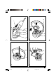
◆ KG70: Place the outer flange (12) onto the
spindle with the raised centre facing towards
the disc (A in fig. F).
◆ KG68/KG75/CD500: Place the outer flange (12)
onto the spindle. When fitting a grinding disc,
the raised centre on the outer flange must face
towards the disc (A in fig. F). When fitting a
cutting disc, the raised centre on the outer
flange must face away from the disc (B in fig. F).
◆ KG68/CD500: Hold the spindle using the
wrench (13) and tighten the outer flange using
the two-pin spanner (14) (fig. G).
◆ KG70/KG75: Keep the spindle lock (3)
depressed and tighten the outer flange using
the two-pin spanner (14) (fig. A & G).
Removing
◆ KG68/CD500: Hold the spindle using the
wrench (13) and loosen the outer flange (12)
using the two-pin spanner (14) (fig. G).
◆ KG70/KG75: Keep the spindle lock (3)
depressed and loosen the outer flange (12)
using the two-pin spanner (14) (fig. A & G).
◆ Remove the outer flange (12) and the disc (5).
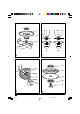
Fitting and removing sanding discs (fig. A, H & I)
For sanding, a backing pad is required.
The backing pad is available from your
Black & Decker dealer as an accessory.
Fitting
◆ Remove the guard as described above.
◆ Place the inner flange (10) onto the spindle (6)
as shown (fig. H). Make sure that the flange is
correctly located on the flat sides of the spindle.
◆ Place the backing pad (15) onto the spindle.
◆ Place the sanding disc (16) onto the backing pad.
◆ Place the outer flange (12) onto the spindle with
the raised centre facing away from the disc.
◆ KG68/CD500: Hold the spindle using the
wrench (13) and tighten the outer flange using
the two-pin spanner (14) (fig. I).
◆ KG70/KG75: Keep the spindle lock (3)
depressed and tighten the outer flange using
the two-pin spanner (14) (fig. A & I).
Removing
◆ KG68/CD500: Hold the spindle using the
wrench (13) and loosen the outer flange (12)
using the two-pin spanner (14) (fig. I).
◆ KG70/KG75: Keep the spindle lock (3)
depressed and loosen the outer flange (12)
using the two-pin spanner (14) (fig. A & I).
◆ Remove the outer flange (12), the sanding disc
(16) and the backing pad (15).
After sanding, refit the guard on the tool.
USE
Let the tool work at its own pace.
Do not overload.
◆ Carefully guide the cable in order to avoid
accidentally cutting it.
◆ Be prepared for a stream of sparks when the
grinding or cutting disc touches the workpiece.
◆ Always position the tool in such a way that the
guard provides optimum protection from the
grinding or cutting disc.
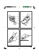
Switching on and off (fig. J)
◆ To switch on, slide the on/off switch (1)
forward.
◆ To switch off, press the rear part of the on/off
switch.
Hints for optimum use
◆ Firmly hold the tool with one hand around the
side handle and the other hand around the
motor housing (fig. K).
◆ When grinding, always maintain an angle of
approx. 15° between the disc and the
workpiece surface (fig. L).
MAINTENANCE
Your Black & Decker tool has been designed to
operate over a long period of time with a
minimum of maintenance. Continuous satisfactory
operation depends upon proper tool care and
regular cleaning.
SAG.P65 17-07-2001, 14:5110