BlackDiamond® 20808 Switch Hardware Installation Guide Extreme Networks, Inc. 3585 Monroe Street Santa Clara, California 95051 (888) 257-3000 (408) 579-2800 http://www.extremenetworks.com Published March 2009 Part number: 126002-00 Rev.
AccessAdapt, Alpine, Altitude, BlackDiamond, EPICenter, Essentials, Ethernet Everywhere, Extreme Enabled, Extreme Ethernet Everywhere, Extreme Networks, Extreme Standby Router Protocol, Extreme Turbodrive, Extreme Velocity, ExtremeWare, ExtremeWorks, ExtremeXOS, Go Purple Extreme Solution, ScreenPlay, Sentriant, ServiceWatch, Summit, SummitStack, Triumph, Unified Access Architecture, Unified Access RF Manager, UniStack, the Extreme Networks logo, the Alpine logo, the BlackDiamond logo, the Extreme Turbodriv
Table of Contents Preface........................................................................................................................................... 7 About this Guide .........................................................................................................................7 Conventions................................................................................................................................7 Related Publications ...........................................
Table of Contents Temperature .................................................................................................................34 Chassis Airflow Requirements.........................................................................................34 Space Requirements for the Switch.................................................................................35 Rack Specifications and Recommendations ...........................................................................
Table of Contents Chapter 7: Installing the BlackDiamond 20808 Modules ................................................................. 73 Required Tools..........................................................................................................................73 Installing Management Modules and I/O Modules.........................................................................74 Removing an I/O Module or Management Module ...................................................................
Table of Contents Appendix B: Technical Specifications .......................................................................................... 125 BlackDiamond 20808 Switch Specifications .............................................................................125 Power Supply Specifications ....................................................................................................127 Connector Pinouts .........................................................................................
Preface This preface provides an overview of this guide, describes guide conventions, and lists other publications that might be useful. WARNING! Only trained service personnel should perform service to Extreme Networks switches and their components. Before installing or removing any components of the system, or before carrying out any maintenance procedures, you must thoroughly read the safety information provided in Appendix A of this guide.
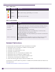
Preface Table 1: Notice Icons Icon Notice Type Alerts you to... Note Important features or instructions. Caution Risk of personal injury, system damage, or loss of data. Warning Risk of severe personal injury. Table 2: Text Conventions Convention Description Screen displays This typeface represents information as it appears on the screen, or command syntax.
Related Publications You can select and download the following Extreme Networks documentation from the Documentation Overview page: ● Software user guides ● Hardware user guides Archived user guides for software are available at: http://www.extremenetworks.com/services/documentation/swuserguides.asp Archived installation guides for hardware are available at: http://www.extremenetworks.com/services/documentation/hwuserguides.
Preface 10 BlackDiamond 20808 Switch Hardware Installation Guide
1 About the BlackDiamond 20808 Switch
1 About the BlackDiamond 20808 Switch This chapter includes the following sections: ● Overview of the BlackDiamond 20808 Switch on page 13 ● BlackDiamond 20808 Chassis on page 13 For information about the I/O modules, management modules (MMs), and switch fabric modules (XFMs) for the BlackDiamond 20808 switch, see Chapter 2, “BlackDiamond 20808 Switch Modules.”. For information about installing the BlackDiamond 20808 switch, see Chapter 3, “Installing the BlackDiamond 20808 Chassis.”.
About the BlackDiamond 20808 Switch ● Five bays for redundant AC or DC power supplies, accessible from the back ● Two fan trays: ● ● ■ One under the front card cage and accessible from the front ■ One above the switch fabric modules and accessible from the back Two connectors for an ESD-preventive wrist strap: ■ One at the top right corner of the front panel ■ One above the right side of the switch fabric modules Air filters for the chassis air intake and for the switch fabric modules Figure
BlackDiamond 20808 Chassis Figure 2 shows the back of the BlackDiamond 20808 chassis.
About the BlackDiamond 20808 Switch 16 BlackDiamond 20808 Switch Hardware Installation Guide
2 BlackDiamond 20808 Switch Modules This chapter includes the following sections: ● Overview of the BlackDiamond 20808 Modules on page 17 ● Management Modules on page 17 ● Switch Fabric Module on page 21 ● I/O Modules on page 21 Overview of the BlackDiamond 20808 Modules Modules for the BlackDiamond 20808 switch include management modules, I/O modules, and switch fabric modules.
BlackDiamond 20808 Switch Modules Redundant Management Module Activity The BlackDiamond 20808 switch can operate with a single management module installed, providing full bandwidth with this single management module. When you install a second management module, one of the management modules operates as the primary, and the other becomes the secondary or backup. The primary management module is responsible for upper-layer protocol processing and system management functions.
Management Modules Figure 3: BlackDiamond 20808 Management Module Management modules have the following features on the front panel: ● Console port—The DB-9 serial console port is used to connect a terminal, allowing you to perform local management. ● Management port—The 10/100 Mbps Ethernet management port allows you to connect an Ethernet cable directly from your laptop to the management port to view and locally manage the switch configurations.
BlackDiamond 20808 Switch Modules Management Module LEDs LEDs on the management module (see Table 4) provide status information about the switch operation and major chassis components. Table 4: LEDs on the Management Module Label/Function Color/State Meaning SYS Green/blinking System has booted and is operating normally. System status Off System is booting or is powered off. MSTR Green/steady Master/backup status of module This management module is the master in the system.
Switch Fabric Module Switch Fabric Module The XFM-1 switch fabric modules (Figure 4) provide the active switching fabric for the switch. Each XFM-1 module provides 384 Gbps total switching capacity. Up to five XFM-1 modules can be installed in dedicated slots at the rear of the BlackDiamond 20808 chassis, providing a total switch fabric capacity of 2 Tbps. Figure 4: XFM-1 Module BD_222 Switch fabric modules have internal fans that provide module cooling independent of the chassis ventilation system.
BlackDiamond 20808 Switch Modules BlackDiamond GM-40XA and GM-40XB I/O Modules The GM-40XA and GM-40XB modules (Figure 5) have forty unpopulated SFP-based Gigabit Ethernet ports. The GM-40XA (advanced) module supports up to 1 million MAC addresses and IP routes. The GM-40XB (basic) module supports up to 512K MAC addresses and IP routes. Both modules have the same physical features.
I/O Modules BlackDiamond XM-8XB Module The XM-8XB module (Figure 6) has eight unpopulated XFP-based 10-Gigabit Ethernet ports. Figure 6: XM-8XB Module BD_221 In the default configuration for the XM-8XB module, all ports: ● Are added to the default VLAN as untagged. ● Inherit the properties of the default VLAN (for example, protocol type and VLANid).
BlackDiamond 20808 Switch Modules I/O Module LEDs Table 6 describes the LEDs on the BlackDiamond 20808 I/O modules. Table 6: LEDs on the BlackDiamond I/O Modules Type Label/Function Color/State Meaning STAT Green/blinking Normal operation. Module status Amber/blinking Configuration error, code version error, diagnostic failure, or other severe module error. Module Off The module is not receiving power. DIAG Amber/blinking Diagnostic tests are in progress.
3 BlackDiamond 20808 Power Supplies This chapter includes the following sections: ● Overview of the BlackDiamond 20808 Power Supplies on page 25 ● AC Power Supply on page 25 ● DC Power Supply on page 27 NOTE For central DC power connections, the 1900 W DC PSU is intended to be installed only in restricted access locations (for example, a dedicated equipment room, equipment closet, or central office) in accordance with Articles 110-16, 110-17, and 110-18 of the National Electric Code, ANSI/NFPA-70.
BlackDiamond 20808 Power Supplies Figure 7: 2500 W AC PSU BD_173 Each 2400 W AC PSU contains two cooling fans at the right of the unit. Airflow enters from the right side vents on the PSU and exits out the left side vents of the switch. Airflow through the PSU is independent from the airflow through the rest of the switch. For information about installing the 2300 W AC PSU, see Chapter 4. LEDs The Extreme Networks 2400 W AC PSU has status LEDs on the front panel.
DC Power Supply Fuse The Extreme Networks 2400 W AC PSU line and neutral legs are both fused. Power to the switch may still be live if the neutral fuse is open. This is not a field operator replaceable fuse. WARNING! Field operators must not attempt to configure or replace fuses in Extreme Networks 2400 W AC PSUs! In the event of failure, immediately return the defective Extreme Networks 2400 W AC PSU for a complete replacement.
BlackDiamond 20808 Power Supplies Each 1900 W DC PSU contains two cooling fans at the right of the unit. Airflow enters from the right side vents on the PSU and exits out the left side vents of the switch. Airflow through the PSU is independent from the airflow through the rest of the switch. To use the 1900 W DC PSU, you need a -48 V DC power source capable of providing 60 A dedicated power to each 1900 W DC PSU installed in the switch. For information about installing the 1900 W DC PSU, see Chapter 4.
2 Installing the BlackDiamond 20808 Switch
4 Site Preparation This chapter includes the following sections: ● Planning Your Site on page 31 ● Meeting Site Requirements on page 32 ● Evaluating and Meeting Cable Requirements on page 40 ● Meeting Power Requirements on page 37 ● Applicable Industry Standards on page 45 By carefully planning your site, you can maximize the performance of your existing network and ensure that it is ready to migrate to future networking technologies.
Site Preparation ● Meeting power requirements To run your equipment safely, you must meet the specific power requirements for each power supply unit installed in the system. For power supply specifications, see Appendix B.
Meeting Site Requirements ● Federal Communications Commission (FCC)—a commission that regulates all interstate and foreign electrical communication systems that originate in the United States according to the Communications Act of 1934. The FCC regulates all U.S. telephone and cable systems. The address is FCC; 445 12th Street S.W.; Washington, D.C. 20554 USA. http://www.fcc.
Site Preparation Temperature Extreme Networks equipment generates a significant amount of heat. It is essential that you provide a temperature-controlled environment for both performance and safety. Install the equipment only in a temperature- and humidity-controlled indoor area that is free of airborne materials that can conduct electricity. Too much humidity can cause a fire. Too little humidity can produce electrical shock and fire.
Meeting Site Requirements Figure 9: Air Flow Through the BlackDiamond 20808 Switch 3 2 1 BD_225 1 = Air flow through the front-installed modules 2 = Air flow through the PSUs 3 = Air flow through the switch fabric modules NOTE When the air baffles are attached to the PSU air vents on the chassis, they modify the air intake and outflow through the PSU bays so that air is pulled from the direction of the chassis front and blown out toward the rear of the chassis.
Site Preparation Figure 10: Space Requirements Around the BlackDiamond 20808 Switch 4 inches (10 cm) 1 BlackDiamond 20808 Chassis 23 inches (58.4 cm) 2 Front Back 29 inches (73.7 cm) 22 inches (56 cm) 3 15 inches (38 cm) 4 inches (10 cm) BD_224 Rack Specifications and Recommendations Racks should conform to conventional standards. In the United States, use EIA Standard RS-310C: Racks, Panels, and Associated Equipment. In countries other than the United States, use IEC Standard 297.
Meeting Power Requirements At a minimum, follow these guidelines to ground equipment racks to the earth ground: ● CAD weld appropriate wire terminals to building I-beams or earth ground rods. ● Use the appropriate chassis grounding wire for your system. The appropriate wire selection depends on the available input current to the power supply. ■ For AC systems using a 20A breaker per PSU, the minimum size for the chassis ground is 14 AWG. The power cable ground should be the same size as the primary.
Site Preparation ● When connecting power to installed equipment, avoid connecting through an extension cord or power strip. ● If your switch includes more than one power supply, connect each power supply to different, independent power sources. If a power source fails, it will affect only the power supply to which it is connected. If all switch power supplies are connected to a single power source, the entire switch is vulnerable to a power source failure.
Meeting Power Requirements Replacing the Power Cord If the AC power cord plug is unsuitable and must be replaced, connect the power supply wires for the switch according to the following scheme: ● Brown wire to the Live (Line) plug terminal, which may be marked with the letter “L” or colored red. ● Blue wire to the Neutral plug terminal, which may be marked with the letter “N” or colored black.
Site Preparation Calculating Volt-Amperage Requirements To determine the minimum volt-amperage requirements for your UPS: 1 Locate the voltage and amperage requirements for each piece of equipment. These numbers are usually located on a sticker on the back or bottom of your equipment. 2 Multiply the numbers together to get Volt-Amps (VA): VA = Volts x Amperes 3 Add together the VA from all the pieces of equipment to find the total VA requirement.
Evaluating and Meeting Cable Requirements Consider the following recommendations when setting up a cable labeling system suitable for your installation: ● Identify cables by securely attaching a label to all cable ends. ● Assign a unique block of sequential numbers to the group of cables that run between each pair of wiring closets. ● Assign a unique identification number to each equipment rack.
Site Preparation Figure 11: Properly Installed and Bundled Cable Cable managers supporting and directing cables Proper bundling of cables Adequate slack, and bend radius SPG_008 Fiber Optic Cable Fiber optic cable must be handled carefully during installation. Every cable has a minimum bend radius, for example, and fibers will be damaged if the cables are bent too sharply. It is also important not to stretch the cable during installation.
Evaluating and Meeting Cable Requirements Figure 12: Bend Radius for Fiber Optic Cable Minimum 2-in. (5.08-cm) radius in 90∞ bend 90∞ Optical fiber cable SPG_002 Cable Distances Table 10 shows cable media types and maximum distances that support reliable transmission in accordance with international standards, except where noted.
Site Preparation RJ-45 Connector Jackets Use RJ-45 cable with connector jackets that are flush with the connector or that have connectors with a no-snag feature. Using cable with jackets that are wider than the connectors can cause: ● Connectors that are not properly aligned with the port. ● Crowded cable installation, which can cause connectors to pop out of the port. Figure 13 shows examples of connector jacket types that are not recommended, as well as those that are recommended.
Applicable Industry Standards Applicable Industry Standards For more information, see the following ANSI/TIA/EIA standards: ● ANSI/TIA/EIA-568-A—discusses the six subsystems of a structured cabling system. ● ANSI/TIA/EIA-569-A—discusses design considerations. ● ANSI/TIA/EIA-606—discusses cabling system administration. ● ANSI/TIA/EIA-607—discusses commercial building grounding and bonding requirements. You can access these standards at: http://www.ansi.org or http://www.tiaonline.
Site Preparation 46 BlackDiamond 20808 Switch Hardware Installation Guide
5 Installing the BlackDiamond 20808 Chassis This chapter provides instructions for installing the BlackDiamond 20808 chassis in an equipment rack. The BlackDiamond 20808 chassis is designed to fit into a standard 19-inch equipment rack. Optional mid-mount brackets allow you to install the chassis in a mid-mount position.
Installing the BlackDiamond 20808 Chassis 2 Open the top flaps of the box and remove the support brackets, boxed accessories, and customer materials package (Figure 15). Lay these items aside until they are needed. Figure 15: Removing the Accessories 3 Remove the top packing foam pieces. 4 Lift the box off the shipping pallet with the chassis. Figure 16: Removing the Top Packing Foam 5 Open the top of the chassis packing bag and slide the bag down around the base of the chassis.
Pre-Installation Requirements Pre-Installation Requirements For detailed information about rack specifications and space requirements, see Chapter 2. CAUTION An unpopulated BlackDiamond 20808 chassis weighs approximately 165 pounds. as shipped. Extreme Networks recommends that you remove all installed blanks and the front fan tray before you install the chassis in the rack. Removing these items will reduce the chassis weight by approximately 44 pounds.
Installing the BlackDiamond 20808 Chassis For an installation in a 4-post rack, you can install the second support bracket across the rear rack posts. Figure 17: Attaching the Support Bracket EX_086B 3 From the front of the rack, lift the back of the empty BlackDiamond 20808 chassis onto the support bracket. 4 Slowly guide the chassis into the equipment rack until the mounting brackets are flush against the rack uprights. 5 Secure the chassis to the equipment rack using 12 rack mounting screws.
Front-Mounting a BlackDiamond 20808 Chassis Figure 18: Securing the Chassis to the Rack BD_197 6 Attach the PSU air baffles to the sides of the chassis, following the instructions in “Attaching the PSU Air Baffles” on page 54. CAUTION Properly installed PSU air baffles prevent the hot PSU exhaust of one system from being drawn into the PSU air intake of an adjacent system, and therefore protect against premature thermal shutdown of the PSU or early power supply failure.
Installing the BlackDiamond 20808 Chassis Mid-Mounting a BlackDiamond 20808 Chassis To mid-mount a BlackDiamond 20808 chassis: 1 On each side of the chassis, align a mid-mount brackets with its mounting holes on the chassis sheet metal. 2 Using a #2 Phillips screwdriver, insert and tighten the mounting screws to secure the bracket to the chassis (Figure 19). Figure 19: Attaching a Mid-mount Bracket BD_198 3 Identify the rack location where the chassis will be installed.
Mid-Mounting a BlackDiamond 20808 Chassis 4 Using four rack mounting screws, attach the support bracket to the equipment rack immediately below the chassis location (Figure 20). (Screws are not provided.) To provide wider support for the chassis as you install it, you can attach the second support bracket on the other side of the rack post. Figure 20: Attaching the Support Bracket EX_086B 5 From the front of the rack, lift the back of the empty BlackDiamond 20808 chassis onto the support bracket.
Installing the BlackDiamond 20808 Chassis 7 Secure the chassis to the equipment rack using 12 rack mounting screws. (Screws are not provided.) Be sure that the screws are secure. Refer to Figure 21 for the screw locations. Figure 21: Securing the Chassis to the Rack (Mid-mount Installation) BD_199 8 Attach the PSU air baffles to the sides of the chassis, following the instructions in “Attaching the PSU Air Baffles.
Grounding the BlackDiamond 20808 Chassis To attach the air baffles: 1 On the side of the chassis, locate the slots for the top and bottom locking tabs. Determine whether the open side of the baffle will face the front or back of the chassis. On the left side (as you face the rear of the chassis), the baffle must open toward the back of the chassis. On the right side, the baffle must open toward the front of the chassis.
Installing the BlackDiamond 20808 Chassis To ground the chassis: 1 Locate the grounding point on the back of the chassis (Figure 23). Figure 23: Back of BlackDiamond 20808 Chassis Chassis grounding point 2 Strip 0.5 inch (1.2 cm) of insulation from the copper wire cable. 3 Insert the stripped wire into the cable lug. 4 Crimp the lug onto the cable according to the manufacturer’s specifications. 5 Insert the screws through the lug and into the grounding point on the back of the chassis.
6 Installing Power Supplies in the BlackDiamond 20808 Switch This chapter describes how to install and remove the power supplies in the BlackDiamond 20808 switch.
Installing Power Supplies in the BlackDiamond 20808 Switch Installing an AC Power Supply To install an Extreme Networks 2400 W AC PSU: 1 Attach an ESD-preventive wrist strap to your bare wrist and connect the metal end to the ground receptacle on the top right corner of the switch front panel. 2 At each side, completely loosen the captive retaining screws and remove the power supply retainer from the chassis (see Figure 24).
Installing a 2400 W AC Power Supply Unit (PSU) 5 Support both sides of the PSU as you carefully slide the unit all the way into the power supply bay (Figure 26). CAUTION Do not slam the PSU into the system switch backplane. Use the latches to secure the PSU in the chassis. Figure 26: Inserting the 2400 W AC PSU into the Power Supply Bay BD_174 6 Secure the 2400 W AC PSU in the power supply bay by rotating the latches toward each other until the unit clicks into place.
Installing Power Supplies in the BlackDiamond 20808 Switch 8 After all the PSUs are installed, re-attach a power supply retainer on each side of the power supply bay as follows: a Set the retainer against the power supply with the rubber cushion toward the power supply and the captive retaining screws aligned with the side of the BlackDiamond 20808 chassis (see Figure 27). b Insert and fully tighten the captive retaining screws.
Installing a 2400 W AC Power Supply Unit (PSU) Figure 28: Connecting Power with a Wire-Style Power Cord Retainer 1 2 3 BD_175 4 Connect the other end of the power cord to a grounded AC power outlet. Leave the ESD strap permanently connected to the switch, so that the strap is always available when you need to handle ESD-sensitive components.
Installing Power Supplies in the BlackDiamond 20808 Switch Figure 29: Connecting Power with the Clamp-Style Power Connector Retainer 2 4 1 5 3 BD_175 2 Connect the AC power cord to the PSU as follows: a Loosen the middle screw of the power cord retainer to allow the power cord connector to slide through it. b Connect the power cord connector to the AC input on the front of the PSU (see Figure 294).
Removing an Extreme Networks 2400 W AC PSU Removing an Extreme Networks 2400 W AC PSU CAUTION The AC PSU may be hot to the touch; use thermal protective gloves when handling the PSU during removal. To remove an Extreme Networks 2400 W AC PSU: 1 Attach an ESD-preventive wrist strap to your bare wrist and connect the metal end to the ground receptacle on the top right corner of the switch front panel. 2 Disconnect the AC power cord from the wall outlet.
Installing Power Supplies in the BlackDiamond 20808 Switch Installing a 1900 W DC Power Supply NOTE Extreme Networks does not recommended using the 1900 W DC PSU in combination with an Extreme Networks 2400 W AC PSU in the same BlackDiamond 20808 system. Required Tools and Materials You need the following tools and materials to install or remove an Extreme Networks 1900 W DC PSU: ● #6 AWG stranded copper cable for connecting the PSU to the DC power source.
Installing a 1900 W DC Power Supply Preparing the Cables Three right-angle lugs (Burndy part number YA6CL1-90, #6 AWG wire lug) are provided with the PSU. You need a crimping tool to attach the lugs to the power and ground cables. To prepare the cables: 1 On each wire, strip 0.5 inch of insulation from one end. 2 Slide a 1-inch piece of heat-shrink tubing over the end of the wire. 3 Insert a stripped wire end all the way into the barrel of a lug (Figure 31) and crimp the lug securely to the wire.
Installing Power Supplies in the BlackDiamond 20808 Switch Figure 32: Removing the Power Supply Retainers 3 If necessary, remove a blank cover from the PSU slot. 4 Verify that the PSU is right side up and the latches are open (see Figure 33). To open the latches, push the spring-loaded catch and rotate the latches away from the front of the PSU.
Installing a 1900 W DC Power Supply Figure 34: Inserting the 1900 W DC PSU into the Power Supply Bay BD_178 6 Secure the 1900 W DC PSU in the power supply bay by rotating the latches toward each other until the unit clicks into place. Make sure that both latches engage properly and that they both latch securely. 7 To install more PSUs, repeat steps 3 through 6.
Installing Power Supplies in the BlackDiamond 20808 Switch Connecting the Ground Cable WARNING! Be sure to connect the chassis ground wire before you connect any power cables. Be sure to disconnect the ground wire after you disconnect all power cables. You need a 3/8-inch driver to tighten the nut on the grounding post. To connect the ground cables: 1 Verify that the DC circuit is de-energized.
Installing a 1900 W DC Power Supply Connecting the PSU to the DC Source Voltage The DC power connection at your facility must be made by a qualified electrician, following the instructions in this section. WARNING! Always make sure that the DC circuit is de-energized before connecting or disconnecting the DC power cables on the 1900 W DC PSU. CAUTION Provide proper connection and strain relief on the DC power cables in accordance with all local and national electrical codes.
Installing Power Supplies in the BlackDiamond 20808 Switch 6 Connect the cables to the DC source voltage, using hardware appropriate to the installation site and following local and national electrical codes. 7 Energize the DC circuit. Leave the ESD strap permanently connected to the switch, so that the strap is always available when you need to handle ESD-sensitive components.
Installing a PSU Blank Slot Cover 7 Use the handle to slide the PSU out of the chassis (Figure 38). Be sure to support both sides of the PSU as you remove it from the chassis. Figure 38: Removing a 1900 W DC PSU BD_179 8 If you are not installing a replacement PSU, install a PSU blank cover over the unoccupied slot. Leave the ESD strap permanently connected to the switch, so that the strap is always available when you need to handle ESD-sensitive components.
Installing Power Supplies in the BlackDiamond 20808 Switch Figure 39: Installing a PSU Slot Cover BD_215 3 Attach the PSU retainer at each side of the chassis (Figure 40 Figure 40: Attaching a PSU Retainer BD_177 72 BlackDiamond 20808 Switch Hardware Installation Guide
7 Installing the BlackDiamond 20808 Modules This chapter describes how to install management modules, I/O modules, and switch fabric modules in the BlackDiamond 20808 chassis. It also describes how to install module blanks in unpopulated chassis slots. Management modules and I/O modules are installed in vertical module slots at the front ot the chassis. Switch Fabric modules are installed in horizontal module slots at the back of the chassis.
Installing the BlackDiamond 20808 Modules Installing Management Modules and I/O Modules All BlackDiamond 20808 I/O and management modules are hot-swappable. You do not need to power the system off to install or remove a BlackDiamond 20808 I/O or management module. To install a module: 1 Attach the ESD-preventive wrist strap to your bare wrist and connect the metal end to the ground receptacle on the top right corner of the chassis. 2 Identify the slot where the module will be installed (Figure 41).
Installing Management Modules and I/O Modules 4 Remove the module from the anti-static packaging as follows: a Place the ESD bag containing the module on a flat ESD surface that is clear of any debris. b Break the quality seal, the ESD warning seal, and the Read Installation Note seal. c Open the ESD bag and carefully remove the module. CAUTION To prevent ESD damage, hold the module by the front panel only. Never touch the components on the PCB or the pins on any of the connectors.
Installing the BlackDiamond 20808 Modules Figure 43: Seating a Module (Management Module Shown) BD_187 8 Using a # 2 Phillips screwdriver, align and tighten the captive retaining screws (Figure 44). When you are installing multiple modules, always secure each installed module before you insert the next adjacent module.
Removing an I/O Module or Management Module 9 Store the module packaging for future use. Leave the ESD-preventive wrist strap permanently connected to the chassis so that the strap is always available when you need to handle ESD-sensitive components. For information about the module LEDs, see “Management Module LEDs” on page 20 and “I/O Module LEDs” on page 24.
Installing the BlackDiamond 20808 Modules 3 Simultaneously rotate the injector/ejector levers away from each other to release the module from the chassis slot (Figure 46). Figure 46: Unseating a Module (Management Module Shown) BD_188 CAUTION To prevent ESD damage, hold the module by the metal panel edges only. Never touch the components on the PCB or the pins on any of the connectors. 4 Carefully slide the module out of the chassis slot (Figure 47). BlackDiamond modules are heavy.
Removing an I/O Module or Management Module Figure 47: Removing a Module (Management Module Shown) BD_186 5 Place the module into the ESD bag to protect it from potential ESD damage. This will also prevent dust from collecting on the module connectors. 6 If a replacement module will not be installed in the chassis slot, install a module blank to ensure that the BlackDiamond20808 chassis maintains proper cooling.
Installing the BlackDiamond 20808 Modules Installing I/O or Management Module Blanks To ensure satisfactory EMI levels and to maintain adequate airflow through the BlackDiamond 20808 switch, always make certain that all module slots contain either an installed module or a module blank. If you remove an installed module, you must install a replacement module or a module blank to ensure that the remaining modules continue to function correctly.
Installing Switch Fabric Modules Figure 49: Securing a Module Blank BD_217 Installing Switch Fabric Modules Five XFM-1 switch fabric modules are installed in dedicated slots at the rear of the BlackDiamond 20808 chassis. To ensure proper cooling of the XFM-1 modules, always make certain that all five XFM-1 module slots contain either an XFM-1 module or an XFM-1 module blank.
Installing the BlackDiamond 20808 Modules 4 Remove the module from the anti-static packaging as follows: a Place the ESD bag containing the module on a flat ESD surface that is clear of any debris. b Break the quality seal, the ESD warning seal, and the Read Installation Note seal. c Open the ESD bag and carefully remove the module. CAUTION To prevent ESD damage, hold the module by the front panel only. Never touch the components on the PCB or the pins on any of the connectors.
Removing a Switch Fabric Module Figure 51: Securing the Switch Fabric Module BD_195 9 Store the module packaging for future use. Leave the ESD-preventive wrist strap permanently connected to the chassis so that the strap is always available when you need to handle ESD-sensitive components.
Installing the BlackDiamond 20808 Modules Figure 52: Loosening the Retaining Screws on the Switch Fabric Module BD_196 3 Simultaneously rotate the injector/ejector levers away from each other to release the module from the chassis slot (Figure 53). Figure 53: Removing a Switch Fabric Module BD_192 CAUTION To prevent ESD damage, hold the module by the metal panel edges only. Never touch the components on the PCB or the pins on any of the connectors.
Installing Switch Fabric Module Blanks 6 If a replacement module will not be installed in the chassis slot, install a blank panel to ensure that the BlackDiamond20808 chassis maintains proper cooling. Leave the ESD-preventive wrist strap permanently connected to the chassis; this is to ensure that the strap is always available when you need to handle ESD-sensitive components.
Installing the BlackDiamond 20808 Modules 86 BlackDiamond 20808 Switch Hardware Installation Guide
3 Maintenance Procedures
8 Packing the BlackDiamond 20808 Chassis for Shipping This chapter describes how to pack the BlackDiamond 20808 chassis for shipment back to Extreme Networks.
Packing the BlackDiamond 20808 Chassis for Shipping c Rotate the open side of the baffle away from the side of the chassis and slip the back edge tabs out of the side air intake grill. Figure 55: Removing an Air Baffle BD_201 3 If necessary, attach the 19-inch support bracket to the equipment rack immediately below the chassis. 4 Remove the chassis from the rack: a Remove the rack mounting screws that secure the chassis to the rack.
9 Cable Management Accessories The BlackDiamond cable manager, cable holders, and cable clips provide a way to organize and contain masses of cables connected to a BlackDiamond switch. This chapter describes how to install and use these cable management accessories.
Cable Management Accessories Figure 56: Cable Manager Components Cable manager cover Cable guides Three screw attachments each side Cable manager base EX_079 The cable manager is shipped assembled. You must remove the cover and the cable guides in order to attach the cable manager base to the rack. To install the cable manager: 1 At the top of the cover, lift the latches as you pull out on the corners to open the cover. 2 Rotate the cover outward and lift it off the base.
Installing the BlackDiamond Cable Manager Figure 57: Cable Guide Screw Locations Screws Hinge tabs fit into cable manager base Top view of open/removed cover EX_181 3 Remove the six screws that secure the cable guides to the mounting base. Save the screws for reattaching the guides later. 4 Set the cable manager mounting base against the rack above the installed BlackDiamond 10808 chassis. Adjust the height of the cable manager base as needed to ensure proper alignment of the screw holes.
Cable Management Accessories Figure 58: Attaching the Cable Manager Base to the Rack Center screws in first Center screws in first EX_076A 6 Reattach the cable guides to the cable manager mounting base using the screws you removed previously (see Figure 59). Do not over-tighten the screws.
Installing the BlackDiamond Cable Manager 7 Route bundled cables through the channels in the cable guides, as shown in Figure 60. Use the cable holders and cable clips to organize and bundle the cables, as described in “Using the Cable Holders and Cable Clips” on page 96.
Cable Management Accessories 8 Set the bottom edge of the cover on the hinge tabs of the cable manager base (see Figure 61). Rotate the cover into place and press firmly at the top until the latches lock.
Using the Cable Holders and Cable Clips Figure 62: BlackDiamond Cable Holders and Clips Interlocking cable holder and cable clips Cable clips Cable holder Side view ENIN005A Connecting Cable Holders Each cable holder holds up to 12 separate cables, with 6 on each side. Connect cable holders end to end as needed to accommodate the number of cables you need to organize. To connect the cable holders: 1 Hold two cable holders as shown in Figure 63.
Cable Management Accessories Figure 63: Connecting Cable Holders ENIN003 2 Slide the ends together and push the cable holders together until you feel them snap into place (see Figure 64). Figure 64: Connected Cable Holders ENIN004 3 Connect as many cable holders together as you need to manage your cable bundles. 4 To disconnect the holders, grasp one in each hand firmly and carefully pull them apart.
Using the Cable Holders and Cable Clips Figure 65: Connecting Cable Clips ENIN001A 3 Press the clips together until l the connectors lock into place (see Figure 66). Figure 66: Cable Clip Chain ENIN002A 4 Connect as many cable clips together as you need to manage your cable bundles. 5 To disconnect the cable clips, push on the bottom ring while holding the top ring steady.
Cable Management Accessories 100 BlackDiamond 20808 Switch Hardware Installation Guide
10 Replacing Ventilation and Airflow Components This chapter describes how to replace fan trays, air filters, and PSU air baffles in the BlackDiamond 20808 Chassis.
Replacing Ventilation and Airflow Components c Carefully slide the fan tray out of the switch chassis (Figure 67). Be sure to support both sides of the fan tray as you pull it free of the chassis. Figure 67: Removing the Fan Tray BD_207 3 Install the replacement fan tray (Figure 68): a Align the replacement tray with the opening in the chassis, and carefully slide the fan tray into the chassis. b Align and tighten the captive retaining screws.
Replacing a Fan Tray Replacing the Rear Fan Tray To replace the rear fan tray: 1 Set the replacement fan tray on a secure work surface. 2 Extend the side rails (Figure 69): a On each side of the fan tray, remove the screws holding the side rails in position. b Holding the faceplate of the fan tray, pull the inner rails out until the two rear holes on the inner rail are aligned with the two holes on the outer rail. c Re-insert the screws to hold the side rails in the extended position.
Replacing Ventilation and Airflow Components Figure 70: Removing the Fan Tray BD_210 5 Install the replacement fan tray (Figure 71): a Align the replacement tray with the opening in the chassis, and carefully slide the fan tray into the chassis. b Align and tighten the captive retaining screw.
Replacing a Chassis Air Filter Replacing a Chassis Air Filter Fans in the BlackDiamond 20808 switch draw cooling air in through the lower front of the chassis and exhaust air through vents at the upper back. A replaceable filter immediately below the front fan tray filters air as it enters the chassis. Required Tools You need a #2 Phillips screwdriver to replace the chassis air filter in the BlackDiamond 20808 switch.
Replacing Ventilation and Airflow Components 2 Pull the old filter out of the chassis (Figure 73) Figure 73: Removing the Air Filter BD_203 3 Identify the orientation arrows on the top of each side rim of the filter. Holding the filter with the orientation arrows pointing toward the switch, slide the filter into the chassis (Figure 74).
Replacing an Air Filter in an XFM-1 Switch Fabric Module 4 Hold the ventilation panel against the front of the switch chassis. Align and tighten the captive retaining screws (Figure 75). Figure 75: Reattaching the Ventilation Panel BD_214 Replacing an Air Filter in an XFM-1 Switch Fabric Module To replace an XFM-1 air filter: 1 Remove the old filter (Figure 76): a Pull outward on one side of the filter frame to detach the frame from the mounting post on the module intake vent.
Replacing Ventilation and Airflow Components Figure 76: Removing a Air Filter from an XFM-1 Switch Fabric Module BD_205 2 Install the new filter (Figure 77): a Push a new filter over the mounting studs on the air intake vent. b Set the frame in place over the new filter and push the frame onto the mounting posts.
Replacing a PSU Air Baffle CAUTION During switch operation, the air baffle on the exhaust side of the PSUs can reach temperatures up to 162° F (72° C). Use thermal protective gloves when you remove air baffles from a functioning switch. To replace a PSU air baffle: 1 Remove the air baffle from the side of the BlackDiamond 20808 chassis: a Use a #2 Phillips screwdriver to completely loosen the captive retaining screws at the top and bottom of the baffle.
Replacing Ventilation and Airflow Components Figure 79: Installing an Air Baffle BD_200 4 Secure the baffle to the chassis using the captive retaining screws at the top and bottom of the baffle.
4 Appendices
A Safety Information WARNING! Read the following safety information thoroughly before installing Extreme Networks products. Failure to follow this safety information can lead to personal injury or damage to the equipment. Only trained service personnel should perform service to Extreme Networks switches and their components.
Safety Information Installing Power Supply Units For the ratings and power requirements of each power supply unit, see Appendix B, “Technical Specifications,”or the data sheet for the power supply at http://www.extremenetworks.com. WARNING! Be sure that the requirements listed in this section are satisfied when installing all Extreme Networks power supplies.
General Safety Precautions ● There are no customer serviceable components in this system. Repairs to the system must be performed by an Extreme Networks factory service technician. ● To remove power from the system, you must unplug all power cords from wall outlets. The power cord is the disconnect device to the main power source. ● Disconnect all power before removing the back panel of any Extreme Networks switch, unless otherwise instructed by a product specific maintenance procedure.
Safety Information Selecting Power Supply Cords Extreme Networks offers selected power input cords for the 2400 W AC PSU. Consult your sales representative for more information about these. The power input cord must meet the following requirements: ● Is agency-certified for the country of use and rated for 200-240 V AC. ● Has an IEC 320 C19 connector for connection to the PSU. ● Has an appropriately rated and approved wall plug applicable to the country of installation.
Battery Replacement and Disposal NOTE Building codes vary worldwide; therefore, Extreme Networks strongly recommends that you consult an electrical contractor to ensure proper equipment grounding and power distribution for your specific installation & country. Battery Replacement and Disposal Batteries included with Extreme products are encapsulated and must be replaced by qualified Extreme Service personnel only. Contact your Extreme Service personnel for product replacement.
Safety Information GBIC, SFP (Mini-GBIC), XENPAK, and XFP Regulatory Compliance ● Class 1 Laser Product ● EN60825-1+A2:2001 or later, European laser standard ● FCC 21 CFR Chapter 1, Subchapter J in accordance with FDA & CDRH requirements ● Application of CE Mark in accordance with 2004/108/EC EMC and 93/68/EEC Low Voltage Directives ● UL and/or CSA registered component for North America ● 47 CFR Part 15, Class A when installed into Extreme products NOTE Extreme Networks optical modules are test
Fiber Optic Ports—Optical Safety Sicherheitshinweise WARNUNG! Vor der Installation der Produkte von Extreme Networks sind die nachfolgenden Sicherheitshinweise aufmerksam zu lesen. Die Nichtbeachtung dieser Sicherheitshinweise kann zu Verletzungen oder Schäden an der Ausrüstung führen.
Safety Information Installation von Netzteilen WARNUNG! Bei der Installation sämtlicher Netzteile von Extreme Networks muss sichergestellt werden, dass die nachfolgend aufgeführten Anforderungen erfüllt sind. Angaben zu Nennleistung und Leistungsbedarf finden sich in den Installationsanweisungen für das jeweilige Netzteil (Power Supply Unit, PSU).
Fiber Optic Ports—Optical Safety zugänglich werden sowie die Gefahr von einem elektrischem Schlag und/ oder Feuergefahr besteht. Nicht die Hand in den Netzteilschacht einführen wenn das Netzteil entfernt ist. Leere Netzteilschächte müssen immer mit eine Abdeckplatte bedeckt sein. Wartungssicherheit Folgende Vorsichtsmaßnahmen müssen getroffen werden: ● Nur für den Einsatz mit diesem System zugelassene Originalzubehörteile bzw. -komponenten verwenden.
Safety Information Auswahl der Stromkabel Je nachdem, welchen Switch Sie erworben haben, werden die Wechselstromnetzteile von Extreme Networks entweder nur mit einem 110-VAC-Kabel oder mit einem 110-VAC-Kabel und einem 208/220VAC-Kabel geliefert. Die von Extreme Networks gelieferten Stromkabel sind nur für den Einsatz in den Vereinigten Staaten und Kanada ausgelegt und zugelassen.
Fiber Optic Ports—Optical Safety ● Schweiz: Der Netzstecker muss der Richtlinie SEV/ASE 1011 entsprechen. ● Großbritannien: Versorgungssteckdose, 15 A, BS 1363 für 110/220-VAC-Netzteile ● International: Versorgungssteckdose, 15 A, CEE 7/7 für 110/220-VAC-Netzteile ● Nur Frankreich und Peru: Diese Einheit kann nicht über IT†-Netzteile mit Strom versorgt werden.
Safety Information 124 BlackDiamond 20808 Switch Hardware Installation Guide
B Technical Specifications This appendix contains the following specifications: ● BlackDiamond 20808 Switch Specifications on page 125 ● Power Supply Specifications on page 127 ● Connector Pinouts on page 128 BlackDiamond 20808 Switch Specifications Table 11: BlackDiamond 20808 Switch Technical Specifications Physical Dimensions BlackDiamond 20808 chassis Height: 25.33 inches (64.34 cm) Width (without rack-mounting brackets): 17.55 inches (44.58 cm) Width (with rack-mounting brackets): 17.
Technical Specifications Table 11: BlackDiamond 20808 Switch Technical Specifications (Continued) EMI/EMC Standards North America EMC for ITE FCC CFR 47 part 15 Class A (USA) 07/10/08; ICES-003 issue 4, 2004-02 (Canada) 108/EC (December 2004) EU EMC directive NEBS GR-1089-Core Issue4, 2006 European EMC standards EN 55022:2006 Class A EN 55024:2006 EN 61000-3-2 v2.1 2001-10 (Harmonics) EN 61000-3-3 v1.1 2002-03 (Flicker) ETSI EN 300 386 V1.4.
Power Supply Specifications Table 11: BlackDiamond 20808 Switch Technical Specifications (Continued) Storage & Transportation Conditions (Packaged) Transportation temperature: –40° C to 70° C (–40° F to 158° F) Storage and transportation humidity: 10% to 93% relative humidity, noncondensing Packaged shock (half sine): <50 kg 180 m/s2 (10 g), 6 ms, 600 shocks, modules >50 kg 100 m/s2 (6 g), 11 ms, 600 shocks, chassis Packaged random vibration: 5 to 20 Hz @ 1.0 ASD w/–3 dB/oct.
Technical Specifications Table 12: Specifications for the 2400 W AC Power Supply (Continued) Operating conditions Operating temperature*: 0° C to 40° C Storage temperature: –40° C to 70° C Operating humidity: 10% to 95% relative humidity, non-condensing Operating altitude: 0 – 10,000 ft (0 – 3,000 m) at 40° C Operational shock: 30 m/s2 (3 g) Table 13: Specifications for the 1900 W DC Power Supply Minimum configuration 1 power supply Maximum configuration 5 power supplies Input Nominal input voltage:
Connector Pinouts Figure 80: Null-modem Cable Pinouts Switch PC/Terminal Cable connector: 9-pin female Cable connector: 25-pin male/female Screen Shell TxD 3 RxD 2 Ground 5 RTS 7 CTS 8 DSR 6 DCD 1 DTR 4 1 3 2 7 4 20 5 6 8 BlackDiamond 20808 Switch Hardware Installation Guide Screen RxD TxD Ground RTS DTR CTS DSR DCD 25pin 129
Technical Specifications 130 BlackDiamond 20808 Switch Hardware Installation Guide
Index Numerics C 10-gigabit Ethernet ports, 23 1900 W DC power supply description, 27 grounding, 68 installing, 64 LEDs, 28 removing, 70 specifications, 128 2400 W AC power supply description, 25 installing, 57 LEDs, 26 removing, 63 specifications, 127 4-post rack, 49 cabinet installation, 36 cable bend radius fiber optic cable, 42 UTP cable, 41 category 5, 41 labeling, 41 management, 91 recommendations for installation, 41 types and distances, 43 cable manager, installing, 92 cabling standards ANSI, 45
Index switch fabric module, 83 XFM-1 module, 83 console port location, 19 pinouts, 128 conventions notice icons, 8 text, 8 D DB-9 pinouts, 128 DC power cable, 65 DC power supply description, 27 grounding, 68 installing, 64 LEDs, 28 removing, 70 specifications, 128 DC power, connecting, 69 design standards, 45 E electrical codes, 32 electrostatic discharge.
Index AC XFM-1 module, 21 replacing, 39 requirements, 38 specifications, 38 M MAC address, identifying, 15 management module dual management modules, 18 features, 19 installing, 74 LEDs, 20 redundant, 18 removing, 77 resetting, 19 management port location, 19 mechanical recommendations for racks, 36 mid-mount installation, 52 MM-Adv module. See management module MM-Base module.
Index wiring closet, 33 reset button, 19 restricted access to DC powered equipment, 28 RF interference patch panel installation, 41 preventing, 44 problems caused by, 44 RJ-45 cable, 44 RJ-45 connector jackets, 44 S safety information in German, 119 safety requirements, 113 See also environmental requirements safety standards, 125 securing the rack, 37 service access to rack, 35 SFP ports, 22 shipping carton, assembling, 90 site planning process, 31 space requirements, rack, 35 specifications power cable,