
User Manual


5
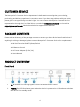
3. IN 1/IN 2: One of the two LEDs will illuminate green when the corresponding input is
selected.
4. OUT 1/OUT 2: Each LED illuminates green when there is an active signal and connection for
the corresponding output.
5. SWITCH: Press the button two switch between the two inputs.
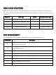
6. EDID: Three DIP switches used to set the EDID®. Refer to the
EDID MANAGEMENT
section for
details.
7.
SERVICE: Micro USB port for performing a firmware update, in the event that a newer
firmware is available.
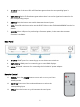
Rear Panel
8.
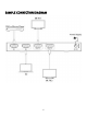
IN 1/IN 2: HDMI® ports for connecting up to two video source devices.
9. OUT 1/OUT 2: HDMI ports for connecting up to two HDMI displays.
10. DC 5V: DC barrel connector for connecting the included AC power adapter.
Remote Control
11.
POWER: Press the POWER button to turn unit on or to put it into
standby mode.
12.
INPUT 1/2: Press one of the numbered buttons to select the
corresponding input.
13. CYCLE: Press the button to cycle between the two inputs.