— C ATA LO G Blackburn® Grounding systems
— Thomas & Betts is now ABB Installation Products, but our long legacy of quality products and innovation remains the same. From connectors that help wire buildings on Earth to cable ties that help put machines in space, we continue to work every day to make, market, design and sell products that provide a smarter, safer and more reliable flow of electricity, from source to socket.
— Table of contents 004 – 005 Overview 006 – 020 EZGround™ compression grounding connectors 021 Cast copper connectors for grounding 022 – 023 Raised floor grounding systems 023 – 024 Ground rod accessories 025 Ground plates 026 – 028 Ground rod clamps 028 Cable tray grounding connector 029 – 032 Structure grounding 033 – 042 Ground clamps
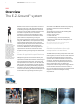
BL ACKBURN GROUNDING S YSTEMS — Overview The E-Z-Ground™ system — 01 This installation method results in a longlasting, low-installed cost connection. You can install it and forget it. Before compression, typical cable connector cross section of cable and connector consists of about 75% metal and 25% air. After ABB method compression, the cross section shows 100% metal with virtually no air spaces.
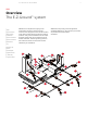
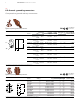
E -Z- G R O U N D S Y S T E M O V E R V I E W 5 — Overview The E-Z-Ground™ system — 1 C-taps — 2 Figure 8 connector — 3 Steel grounding stud TBG series — 4 Figure 6–8 connectors — 5 Figure 6–6 connectors — 6 GG connectors — 7 Lug — 8 Splice/two-way connector — 9 Grounding plate — 10 Pigtail connectors — 11 I-beam clamp — 12 Figure 6 connector ABB offers its complete line of grid-ground compression connectors.
BL ACKBURN GROUNDING S YSTEMS 6 — E-Z-Ground™ grounding connectors Compression ground rod tap connectors DB — Figure 6 compression ground rod tap connector Application Cat. no. Diagrams Main Tap H H Main Main Tap Tap T TT Cable to rebar application A ground B cable rod (in.) range Meets IEEE 837 requirements Dimensions (in.) Dies for TBM14M, H 13100A or TBM15I Main Tap 54855 1/0 str.–250 kcmil or 1⁄2"– 5⁄8" rod #4 sol.– #2 str. #3 rebar 3⁄ 8 thru 1 ⁄ 2 #4 rebar #4 sol.– #2 str.
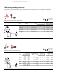
E -Z- G R O U N D G R O U N D I N G C O N N E C TO R S — E-Z-Ground™ grounding connectors Compression ground rod to grid connectors & compression ground grid connectors A ground rod (in.) Cat. no. Diagrams Element A Element A TT TT L L D D Element B Element B LL Meets IEEE 837 requirements DB — Figure 6 to 8 compression ground rod to grid connectors Dimensions (in.
BL ACKBURN GROUNDING S YSTEMS — E-Z-Ground™ grounding connectors Cable-to-cable or cable-to-rod connectors One-piece construction for cable-to-cable, cable-to-rod, “T” and “X” connections. • Suitable for direct burial or in concrete • Replaces exothermic welds • Made from high-conductivity wrought copper • Conforms to IEEE 837 standard • UL® 467 — Cable-to-cable or cable-to-rod connectors DB Cable to cable range Cat. no.
E -Z- G R O U N D G R O U N D I N G C O N N E C TO R S — E-Z-Ground™ grounding connectors Type GRD – Cable-to-cable connector For copper cable-to-cable ground-grid connections. • Cast of high-conductivity bronze alloy • Suitable for direct burial DB — Type GRD – Cable-to-cable connector Conductor size Cat. no. GRD2 GRD20 Main Tap Min. (mm 2) Max. Min. Max. Min. (AWG) (AWG) (mm 2) (mm 2) Max. Min. Max. (mm 2) #1 #2 42.4 33.6 #1 #2 42.4 33.6 2/0 1/0 67.4 53 2/0 1/0 67.
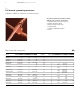
BL ACKBURN GROUNDING S YSTEMS — E-Z-Ground™ grounding connectors Two cables-to-ground rod connector – Heavy-duty cast copper For connecting perpendicular runs of stranded copper cable to ground rod. — Two cables-to-ground rod connector – Heavy-duty cast copper †† Cable size Cat. no. 53065-58GR 53065-34GR Main Tap 250 or 4/0 250 or 4/0 250 or 4/0 DB Ground rod dia. (in.) TBM15I die for cable code 5 ⁄ 8 & 1⁄ 2 250 or 4/0 3 ⁄4 Overall dimensions (in.
E -Z- G R O U N D G R O U N D I N G C O N N E C TO R S — E-Z-Ground™ grounding connectors Grounding grid connectors – Heavy-duty cast copper 53055 53065 — Grounding grid connectors – Heavy-duty cast copper †† DB Rod to cable range Cat. no. Cable to cable range Rod to cable installing die code for TBM14M, 13100A or TBM15I Overall dimensions (in.) Rod size (in.
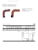
BL ACKBURN GROUNDING S YSTEMS 12 — E-Z-Ground™ grounding connectors C-taps & copper C-crimps DB — C-taps Meets IEEE 837 requirements Main (AWG) Tap (AWG) H L Dies for TBM14M 13100A or TBM15I * #6 sol.–#2 str. #6 sol.–#2 str.** 1.16 0.75 HBKC 1 CTP202 #1 str.–2/0 str. #6 sol.–#2 str.** 1.41 0.75 15501A 1 CTP2020 #1 str.–2/0 str. #1 str.–2/0 str. 1.54 0.75 15501A 1 CTP25020 3/0 str.–250 kcmil #6 sol.–2/0** 1.97 0.75 15G86R 1 CTP250250 Dimensions (in.) Cat. no.
E -Z- G R O U N D G R O U N D I N G C O N N E C TO R S — E-Z-Ground™ grounding connectors Copper C-type compression taps & pigtail connectors Perform line tap-offs, dead-ending and grounding on a range of conductors.
BL ACKBURN GROUNDING S YSTEMS 14 — E-Z-Ground™ grounding connectors Ground plates — Ground plates DB Cat. no. Meets IEEE 837 requirements Fig. Cable range H (in.) Dies GP2250-2 1 #2 AWG–250 kcmil 35⁄ 8 15G86R GP2250-4 2 #2 AWG –250 kcmil 47⁄ 32 15G86R GP250500-2 1 250–500 kcmil 35⁄ 8 15G126R GP250500-4 2 250–500 kcmil 47⁄ 32 15G126R Diagrams 1 3⁄4" 2"X 1⁄2 "-13 UNC 3 1⁄4" ⁄4" 3 2" 4"X 1⁄2 "-13 UNC 1 3⁄4" 5 25⁄32 " ⁄8 "-16 UNC 3 ⁄8 "-16 UNC 3 H Fig.
E -Z- G R O U N D G R O U N D I N G C O N N E C TO R S — E-Z-Ground™ grounding connectors Type TBGS – Structural grounding studs Knurling ensures excellent mechanical pull-out and electrical continuity.
BL ACKBURN GROUNDING S YSTEMS — E-Z-Ground™ grounding connectors I-beam ground clamp & cast copper two-way connector – Heavy-duty Connect ground cable to I-beam or any 1" maximum structural steel member – without welding or drilling.
E -Z- G R O U N D G R O U N D I N G C O N N E C TO R S — E-Z-Ground™ grounding connectors Ground clamps Provides a permanent, reliable connection.
BL ACKBURN GROUNDING S YSTEMS — E-Z-Ground™ grounding connectors Grid-to-fence ground clamp & bus bar connector Bond copper conductors to steel or aluminum fence post or top rail of round fence posts. • Provides quick, dependable installation at low installed cost • Uses no incendiary materials • Body made from cast copper alloy with steel U-bolt — Grid-to-fence ground clamp Cat. no. Ground cable range (AWG) Die code FG2040R2 2/0–3/0–4/0 str. 76 2 FG2040R25 2/0–3/0–4/0 str.
E -Z- G R O U N D G R O U N D I N G C O N N E C TO R S — E-Z-Ground™ grounding connectors SnapTap™ connector A “snap” to assemble – No special tools required.
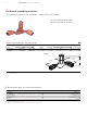
BL ACKBURN GROUNDING S YSTEMS — E-Z-Ground™ grounding connectors SnapTap™ connector (continued) — 01 Fig. 1 — 02 Fig. 2 — 03 Fig. 3 — 04 Fig. 4 — General usage instructions Bend back and forth to separate Separation point Body piece Separate No special tools required. Use ordinary parallel jaw pliers to separate the connector into two parts. Hold one side of connector with pliers and bend opposite side back and forth until parts separate (see Fig. 1).
C A S T C O P P E R C O N N E C TO R S F O R G R O U N D I N G — Cast copper connectors for grounding Riser cable flag connectors for 600 V applications A low-cost method of connecting directly to bus bar, eliminating an interface connection. • Made from high-conductivity wrought copper, plain finish • All bolt holes are 3⁄8" on 1" centers — Riser cable flag connectors for 600 V applications Cat. no. Fig. no.
BL ACKBURN GROUNDING S YSTEMS — Raised floor systems Signal reference grid connector & clamp Compresses #8 AWG through 4/0 AWG cable. • Clamps onto pedestal posts up to 1" diameter square and 1 1⁄4" round • Can be used as an “X” or “T” configuration cable to post • High-conductivity wrought-copper construction — Signal reference grid connector Installing tools and die codes TBM14M and TBM15I Cat. no. Conductor (AWG) Die cat. no.
R A I S E D F LO O R S Y S T E M S A N D G R O U N D R O D A C C E S S O R I E S — Raised floor systems and ground rod accessories Ground electrode boxes, Type C – Sectional ground rod couplings & Type DS – Driving studs — Ground electrode boxes Wt./100 Cat. no. Description lb. kg Standard package 51628 Pregalvanized steel 1180 536.3 5 51629 Hot-dip galvanized 1200 545.4 5 14-gauge steel. 10" diameter, 12" depth. Streamlined design reduces driving friction.
BL ACKBURN GROUNDING S YSTEMS — Ground rod accessories and ground plates Threadless couplings and driving cap & galvanized ground plates For joining non-threaded, copper-bonded steel ground rods. • Couplings manufactured of high-strength, corrosion-resistant copper alloy • High-strength hardened steel driving cap prevents “mushrooming” of ground rod while driving to ensure proper fit of coupling — Threadless couplings and driving cap Dimensions (in.) Cat. no.
G R O U N D P L AT E S — Ground plates Type GP – Copper pole bottom ground plates for multigrounded neutral construction & Type PB – Copper pole ground plates More efficient than butt-wrapping poles. • Made of electrolytic sheet copper • Built-in high-pressure connector for ground lead, or supplied with #6 AWG copper pigtail pre-attached • Plates are grooved for trapping moisture — Type GP – Copper pole bottom ground plates for multigrounded neutral construction Pigtail wire range Cat. no.
BL ACKBURN GROUNDING S YSTEMS 26 — Ground rod clamps Type JWR – Wide-range ground rod clamp & Type JAB – Ground rod clamps UL® listed for both copper-clad and galvanized ground rods. • UL listed for direct burial in earth/concrete • Constructed from bronze alloy and high-performance stainless steel bolt • Provides wide range of connection sizes • More than 300 lbs. DB torque capacity — Type JWR – Wide-range ground rod clamp Wire range Nominal rod dia. Cat. no. JWR Dimensions (in.) (in.) (mm) Max.
GROUND ROD CL AMPS — Ground rod clamps Type G – Budget-line ground clamps & Types GG and GGH – Heavy-duty ground rod clamps A dependable ground connection offered at a substantial savings. • Cast of high-strength corrosion-resistant copper alloy • Furnished with hex head bolts • Simplified, compact design makes lasting, trouble-free connection DB • UL® Listed for direct burial — Type G – budget-line ground clamps Wire range Nominal rod dia. Cat. no. Dimensions (in.) (in.) (mm) Max. (AWG) ⁄8 9.
BL ACKBURN GROUNDING S YSTEMS — Ground rod clamps Type DGC – Drive-on ground clamps & cable tray grounding connector Drive-on design provides easy, tool-free installation, high-reliability compression-fit connection and room for one or two ground leads. • High-strength copper alloy provides increased tensile strength and long-term corrosion resistance for direct-burial applications • UL® 486A and UL 467 Listed • RUS listed DB — Type DGC – Drive-on ground clamps Cat. no.
STRUCTURE GROUNDING — Structure grounding Type GTC – Tower ground clamps & CTG250 wide-range tower ground clamp Bolt features square shank to prevent turning and enable clamp to be tightened with a single wrench.
BL ACKBURN GROUNDING S YSTEMS 30 — Structure grounding Aluminum lay-in lug connector & copper lay-in lug connector Dual-rated for both copper and aluminum conductor. • Manufactured from 6061-T6 aluminum alloy for maximum strength and conductivity • Open-faced design enables installer to quickly lay-in grounding conductor as jumper to multiple conduits with no break in ground conductor — Aluminum lay-in lug connector Dimensions Cond. range Cat. no. Fig. no. (AWG) Stud size (mm2) in. H W (mm) in.
STRUCTURE GROUNDING — Structure grounding Service post connectors Designed for grounding one or two cables to steel structure or transformer.
BL ACKBURN GROUNDING S YSTEMS 32 — Structure grounding Service post connectors (continued) — Single- and double-conductor service post connectors, long stud Conductor range AWG (mm2) Cat no. Stranded Solid Dimensions (in.) Max. Min. Max. Min. Diameter range (in.) SP0DL 8 (6) 12 (4) 8 (10) 12 (4) .146–.081 – 1 11 13 ⁄16 1 55 15 SP1SL SP1DL 7 (10) 10 (6) 6 (10) 10 (6) .164–.102 – 1 ⁄4 –20 x 1 13 31 ⁄ 32 1 55 ⁄ 64 15 SP2SL SP2DL 5 (16) 10 (6) 4 – 10 – .206–.
GROUND CL AMPS — Ground clamps Type GUV – U-Bolt ground clamps Excellent for connecting multiple electrodes with a single cable, such as in substation grounding.
BL ACKBURN GROUNDING S YSTEMS 34 — Ground clamps Water pipe ground clamps & aluminum water pipe clamp — Water pipe ground clamps Cat. no. Ground wire size (AWG) 2-TB Water pipe size (in.) #6, #4, #2 ⁄2, 3⁄4 , 1 or rebar 4-10 1 3-TB 11⁄4 , 11⁄2 or 2 4 21⁄2, 3 or 31⁄2 5-TB 4, 41⁄2 or 5 6 6 Malleable iron. #6 – #2 AWG ground wire. Ground wire size (AWG) Cat. no. 3902 Water pipe size (in.) #4–4/0 Ground wire size (AWG) Cat. no. Water pipe size (in.
GROUND CL AMPS — Ground clamps Die-cast clamps & cast bronze clamps with copper strap Economically priced clamps. • Made of die-cast zinc alloy with zinc-plated screws • Model BJA for use with armored cable — Die-cast clamps Conductor range (AWG) Cat. no. Water pipe size (in.) Max. Min. ⁄2 –1 #2 str. #10 sol. ⁄2 –1 #6 #8 BJ-1 1 BJA* 1 * Not UL listed Flexible copper strap makes alignment easy.
BL ACKBURN GROUNDING S YSTEMS — Ground clamps Cast bronze ground clamps & Type J – Cast bronze ground clamps Connects copper ground wire to water pipe or copper tubing. • High-strength, high-conductivity copper alloy (over 80% copper) • UL® 467 listed for direct burial — Cast bronze ground clamps DB Cat. no. Water pipe size (in.) JD Conductor range (AWG) ⁄2 –1 #2 str.–#10 str. 11⁄4 –2 #2 str.–#10 str. 1 J2D For connecting grounding conductor to water pipe or copper tube.
GROUND CL AMPS — Ground clamps Budget price cast bronze clamp & Type JDLI – Direct-burial ground clamp Similar to aluminum water pipe clamp but lighter in construction. — Budget price cast bronze clamp Cat. no. JJR Conductor range (AWG) Water pipe size (in.) ⁄2 –1 1 Dimensions (in.) Max. Min. A #4 str. #10 sol. 215⁄32 Diagrams B C ⁄32 ⁄32 25 17 B A (max.) C Add suffix C to cat. no. to specify plating.
BL ACKBURN GROUNDING S YSTEMS 38 — Ground clamps Cast bronze clamp & cast bronze clamps for conduit For connecting armored cable to water pipe. • Clamping portion similar to standard “J” clamp • Special pressure bar grips armor or outer cable insulation to reduce chance of grounding conductor being pulled out • Furnished with zinc-plated screws — Cast bronze clamp Water pipe Conductor range (AWG) size (in.) Max. Min. Cat. no. Diagrams JA D G E Dimensions (in.) A B 211⁄32 25 13 ⁄2 –1 #6 sol.
GROUND CL AMPS — Ground clamps Type JPT – Cast bronze clamps for conduit, conduit hubs & Type CH – Bronze conduit hubs Hub swings 360° for ease of alignment. • Pipe clamping portion identical to “JA” clamp • Pressure-bar type conduit hub adjusts to fit 1⁄2 " or 3⁄4" EMT or 1⁄2 " rigid conduit • Brass washer provides positive contact with grounding conductor • Furnished with zinc-plated screws — Type JPT – Cast bronze clamps for conduit Conductor range (AWG) Cat. no. JPT JPT2 Conduit size (in.
BL ACKBURN GROUNDING S YSTEMS 40 — Ground clamps Ground clamp 3826 3849 3840-TB — Ground clamp Cat. no. Material Water pipe, copper tubing size (in.) 3826† M.I. 1 3846 † Bronze 1 3849• Brass 1 M.I. 1 3840-TB* ⁄2, 3⁄4 1 ⁄2 –1 ⁄2, ⁄4 1 ⁄2 –1 3 ⁄2 –1 O.D. – ⁄2, 3⁄4 or 1 – For unarmored copper wire #6, #4. • For copper and aluminum conductors; for 14 thru 2 cu. unarmored copper wire – Corrosive and outdoor use. UL® approved for direct burial. * #8 thru #4 AWG.
GROUND CL AMPS — Ground clamps Ground clamps for K&L grade copper tubing only & cable tray ground clamp — 01 For armored and unarmored wire – 3844 — 02 Disconnect static ground clamp and lug, straight-type (cable not supplied), UL not applicable – 31215 — 03 For radio, motor frame and equipment grounding – 961 — 01 — 02 — 03 — Ground clamps for K&L grade copper tubing only Cat. no. 3844* 3888 Water pipe & ground rod size/desc. (in.
BL ACKBURN GROUNDING S YSTEMS — Ground clamps Tray clamps & beam grounding clamp For aluminum and steel cable trays with regular or reinforced flanges. • Serrations and biting teeth on clamping saddle provide a high-quality bond between conduit and clamp • Can be clamped to any position in a 90° arc • Hardened steel screws bite into tray and provide positive bond • Malleable iron hub and steel U-bolt accept conduit from any angle — Tray clamps Cat. no. Clamp type Conduit size (in.
N OT E S — Notes 43
— Notes BL ACKBURN GROUNDING S YSTEMS
N OT E S 45
BL ACKBURN GROUNDING S YSTEMS Additional information We reserve the right to make technical changes or modify the contents of this document without prior notice. With regard to purchase orders, the agreed particulars shall prevail. ABB AG does not accept any responsibility whatsoever for potential errors or possible lack of information in this document. We reserve all rights in this document and in the subject matter and illustrations contained therein.
— US ABB Installation Products Electrification Products division 860 Ridge Lake Blvd. Memphis, TN 38120 +1 901-252-5000 © Copyright 2018 ABB. All rights reserved. Specifications subject to change without notice. 7TKK000131 REV A 21.9.2018 tnb.abb.