
User Manual


7
EN
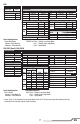
Servo Setup
FUNCTION LISTSYSTEM SETUP
DX8
SYSTEM SETUP
Model Type Airplane
F-Mode Setup
Switch 1 Switch B
Switch 2 Inhibit
Channel Assign
Channel Input
1 Throttle N/A
2 Aileron N/A
3 Elevator N/A
4 Rudder N/A
5 Gear B
6 AUX 1 I
Throttle Cut
Position –130
Switch Switch H
0
1
Throttle Cut
Switch Mix 1
Chan Travel Reverse
THR 100/100 Normal
AIL 100/100 Normal
ELE 100/100 Normal
RUD 100/100 Normal
GER 100/100 Normal
Chan Travel Reverse
AX1 100/100 Reverse
AX2 100/100 Normal
AX3 100/100 Normal
AX4 100/100 Normal
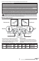
Servo Setup
FUNCTION LIST
DX6, DX7 (Gen 2), DX9, DX18
Timer
Mode Count Down
Time 5:00
Start Throttle Out
Over 25%
One Time Inhibit
D/R & Expo
Chan
Switch (F) Pos
D/R Expo*DX6
DX7, 9,
18
AILE
0 0 100/100 0
1 100/100 0
1 2 75/75 0
ELEV
0 0 100/100 0
1 100/100 0
1 2 75/75 0
RUDD
0 0 100/100 0
1 100/100 0
1 2 75/75 0
D/R & Expo
Chan
Switch Pos (AIL D/R)
D/R
Expo*
AILE
0 100/100 0
1 100/100 0
2 75/75 0
ELEV
0 100/100 0
1 100/100 0
2 75/75 0
D/R & Expo
Chan
Switch Pos (AIL D/R)
D/R
Expo*
RUDD
0 100/100 0
1 100/100 0
2 75/75 0
Timer
Mode Count Down
Time 5:00 Tone
Start Throttle Out
Pos 25%
Chan Travel Reverse
THR 100/100 Normal
AIL 100/100 Normal
ELE 100/100 Normal
RUD 100/100 Normal
Chan Travel Reverse
GER 100/100 Normal
AX1 100/100 Reverse
AX2 100/100 Normal
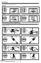
Panic Mode Operation
Trainer/Bind Button
Pressed = Panic Mode On
Released = Panic Mode Off
Model Type ACRO
SW Select
Trainer Aux 1
F Mode Gear
All Others INH
Panic Mode Operation
Bind / I Button
Pressed = Panic Mode On
Released = Panic Mode Off
* Use of "Expo" is not necessary for successful fl ight of the 120 S. The pilot may adjust this setting to tailor the
sensitivity of the helicopter around neutral if desired.
Flight Mode Operation
F MODE Sw: Pos 0 = Stability, Low-Angle Mode
Pos 1 = Stability, High-Angle Mode
Pos 2 = Agility Mode
Flight Mode Operation
Sw B: Pos 0 = Stability, Low-Angle Mode
Pos 1 = Stability, High-Angle Mode
Pos 2 = Agility Mode