Service Manual PB-SM804SA,SM804SB PB-SM806,SM807,SM808 TPB-450EX Date 03-31-03 Revison 002 Electric PowerBoard ISM, Inc. • 1028 4th Street SW • Auburn, WA 98001 • Phone: (253) 333-1200 • Fax: (253) 333-1212 www.tanaka-usa.com custsvc@tanaka-ism.
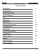
XTR Electric Powerboard Service Manual Table of Contents Specifications 2 Troubleshooting 3 Safety & Shop Practices 4 Routine Maintenance 4 Tools 5 Brake System 6 Wheel Removal 7-8 Steering Head Components 9-12 Chain Maintenance 13 Deck Removal 14 Electric Drive Components 15-16 Circuit Breaker 16 Cables / Controls 17-18 Batteries 19 Electric Drive Motor 20 Warranty Statement 21 www.tanaka-usa.com 1 custsvc@tanaka-ism.
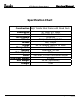
XTR Electric Powerboard Service Manual Specification Chart Construction High Tensile Steel Frame with Wood Deck Dimensions Tires Tire Pressure Wheels Brakes Range Charge Time Battery Drive System Motor Max Rider Weight Unit Weight Charger www.tanaka-usa.com 40” High, 9.5” Wide 10” Kenda Pneumatic 50-60 psi Composite Core Split Rim Disc, Caliper 60-75 Minutes, Approx. 12 Miles 4-5 Hours Lead Acid, 24 Volt Chain 450 Watt, 24 Volt Continuous Output 270 lbs. 55 lbs.
XTR Electric Powerboard Service Manual Trouble Shooting The following guide will help provide a logical sequence to quickly identify problematic areas of the PowerBoard to facilitate repair. Always bear in mind that the majority of electrical symptoms are actually the result of a problem with the chassis of the unit. Before beginning the troubleshooting of the electrical system, inspect the following: 1. Tires - Make sure they are properly inflated.
Service Manual XTR Electric Powerboard Safety & Shop Practices The most successful and profitable service shops consistently seem to maintain the best habits of safety, cleanliness, and orderly procedure. The following information is intended as a guide towards developing habits that are necessary to accomplish satisfactory service work. o Maintain a clean and orderly work area that is well lighted and adequately ventilated.
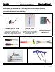
Service Manual XTR Electric Powerboard Tools The following is a minimum list of tools required to service the XTR-S Electric PowerBoard. Other tools may be preferable; however, complete service can be performed with the tools indicated below: Test Wire (Part No. 31644) This is a switch that is also a replacement part on some models of XTR-S PowerBoards. It plugs into the circuit board and serves as a special tool in diagnosing problematic functions.
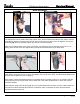
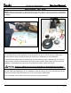
XTR Electric Powerboard Service Manual Brake Adjustment Figure 1 Figure 2 Two adjustments can be made to the brake system. First, use the adjustment located on the caliper, near the wheel (Fig. 1). Begin by loosening the lock-nut with an 8mm wrench, and then turn the adjuster out (counterclockwise) (Fig. 2). Once adjusted, tighten the lock nut to hold that position. Make sure the brake caliper is not loose. Conversely, over-tightening will not allow the wheel to turn.
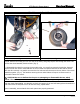
XTR Electric Powerboard Service Manual Wheel Removal - Front Wheel Figure 5 Figure 6 The front wheel is held in place with a solid axle, and can be removed with two 17mm wrenches and/or sockets. Remove the locking nut from one side of the wheel, and gently tap the axle through the wheel. This will free the wheel assembly from the frame. (Fig. 5) To disassemble the wheel for servicing the tire and/or tube, you must first remove the brake disc. Removal requires a 4mm hex wrench.
XTR Electric Powerboard Service Manual Wheel Removal – Rear Wheel NOTE: Extreme caution should be used when servicing the drive chain or rear wheel. Service or maintenance involving the chain should ONLY be performed when power to the electric motor has been disconnected from the battery. Figure 7 Figure 8 Begin by removing the axle lock-nut with a 17mm wrench or socket. Gently tap the axle through the wheel.
XTR Electric Powerboard Service Manual Steering Head Components / Rigid Fork Model Figure 9 Figure 10 Disassembly: First, remove the two bolts, four spacers and lock nuts that secure the forks to the steering head. This requires either a 5mm or 6mm hex wrench, and a 13mm wrench or socket. Remove the lock nuts on the bolts, and gently tap them through the steering head assembly (Fig. 9). Use caution not to damage the threads as you remove the bolts. With the entire front wheel and forks removed (Fig.
XTR Electric Powerboard Service Manual Steering Head Components / Rigid Fork Model cont. Figure 11 Figure 12 Slide the upper cap up the handlebar stem, and out of the way. Remove the lower cap. Removal of these caps reveals the large, 40mm nuts that secure the steering head assembly from the top and bottom. It is not necessary to remove the large top nut. The steering head is held in place by two bottom 40mm nuts.
XTR Electric Powerboard Service Manual Steering Head Components / Suspension Fork Model Note: The suspension forks used on the XTR-S models are designed to accommodate a wide range of riders and terrain and are NOT adjustable. WARNING: Never attempt to disassemble the lower fork tubes. They contain a factory installed spring under considerable tension. Disassembling the forks will release the spring and cause serious injury or death.
XTR Electric Powerboard Service Manual Steering Head Components / Suspension Fork Model Figure 15 Figure 16 Next, remove the three pinch bolts that attach the upper and triple clamp supports to the fork tubes and the steering head, (fig. 15), followed by removal of the bearing adjustment nut, (fig.16). With these components removed, the fork unit can be removed from the steering head through the bottom.
XTR Electric Powerboard Service Manual Chain Maintenance Figure 16 Figure 17 The XTR uses a number 25 drive chain to supply power to the rear wheel. (Fig. 16) Extreme caution should be used when servicing the drive chain. Service or maintenance to the chain should ONLY be performed when power to the electric motor has been disconnected from the battery. The chain should be lubricated at regular intervals.
XTR Electric Powerboard Service Manual Deck Removal Figure 20 The XTR deck is secured to the frame with 10 bolts, (standard wood version – aluminium billet decks have less fasteners), requiring a 4mm hex wrench and a 10mm open-end wrench. Some of these bolts are secured on the bottom side with locking nuts, and some of the bolts are simply threaded into the frame itself. For those bolts secured with nuts on the underside, remove the nuts prior to attempting to remove the bolts from the top.
XTR Electric Powerboard Service Manual Electric Drive Components The following section will help to identify the components, and conduct tests to identify problems within the electrical system. General System Description The XTR electric PowerBoards use two 12 Volt batteries in tandem to supply current to a 450 Watt continuous electric motor, (300 Watts on the earliest version).
XTR Electric Powerboard Service Manual General System Description (cont.) Functions controlled by the circuit board include the charger, the throttle lever, the brake lever, and on some models, the kickstand, indicator light and on/off switch. Circuit Breaker Figure 23 Figure 24 Figure 25 The circuit breaker is attached to the batteries only. It is intended to shut off power to the system in the event the motor is overloaded. This can be the result of several different factors.
XTR Electric Powerboard Service Manual Cables / Controls On the XTR PowerBoard, the front disc brake and throttle are cable actuated. Cables should be periodically inspected to ensure that they move smoothly, and offer full range of motion in order to maximize braking ability and full range of throttle. Cables that have been kinked, corroded, frayed or worn significantly should be replaced. Brake Figure 26 Figure 27 The brake lever mounted to the handlebar actuates the front disc brake.
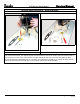
XTR Electric Powerboard Service Manual Cables / Controls Cont The throttle, or speed, is actuated by the right hand lever on the handlebars, and allows power to flow from the batteries to the electric motor. Some models have a throttle that is variable speed control as depicted in fig. 29, while some simply are on/off as shown in fig. 30. Figure 29 Figure 30 To test the throttle lever function, first remove the deck from the frame. Next, identify the wire from the lever to the circuit board.
XTR Electric Powerboard Service Manual Batteries The batteries in the XTR-S models are maintenance free type and can be permanently damaged if the outer case is opened for any reason. Warning: Batteries contain sulphuric acid (electrolyte) which is highly corrosive and poisonous. Getting electrolyte in your eyes or on your skin can cause serious burns. Wear protective clothing and eye protection when working near batteries. KEEP CHILDREN AWAY FROM BATTERIES.
XTR Electric Powerboard Service Manual Electric Drive Motor Figure 33 Figure 34 The electric motor that provides power to the rear wheel is a 450 Watt (300 Watt on earliest models), continuous cycle motor, connected to the batteries via two lead wires. Typically, the motor either works, or does not. After you are confident that the batteries are accepting and retaining a full charge, it is easy to test the motor.