
Service manual

XTR Electric Powerboard
Service Manual
www.tanaka-usa.com custsvc@tanaka-ism.com
Revison 002
6
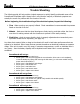
Brake Adjustment
Figure 1 Figure 2
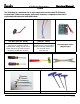
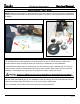
Two adjustments can be made to the brake system. First, use the adjustment located on the caliper, near the
wheel (Fig. 1). Begin by loosening the lock-nut with an 8mm wrench, and then turn the adjuster out (counter-
clockwise) (Fig. 2). Once adjusted, tighten the lock nut to hold that position.
Make sure the brake caliper is not loose. Conversely, over-tightening will not allow the wheel to turn. Full
braking action should occur with approximately one-third to two-thirds throw of the brake lever.
Figure 3
Figure 4
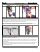
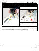
The design of the brake lever (mounted on the handlebar), provides another type of adjustment to the brake
cable. Simply loosen the lock nut, and turn the adjuster out (counter clock-wise), until the desired adjustment is
reached, then re-tighten the lock nut (Fig. 3).
When neither of these adjustments allows an acceptable amount of braking action, it’s an indication that the
brake pads may be worn beyond their service limits and or the cable has stretched. In either case, spares
should be installed.
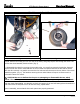
Brake pads are simply slid into place (Fig. 4), but it requires that tension be taken off of the cable to allow the
new pads to be fitted. Note that the pads are not identical, and it is necessary to match the pad with the
appropriate brake actuator arm.