
Instruction manual


8
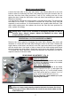
REAR BRAKE PADS REPLACEMENT (Fig. 7 )
First, screw in the adjusting screw on the left brake lever on the handlebars. Loosen
the nuts (M5 - 914.003.01) holding the brake body to the brake holder, and pull the
brake body, rearward. Do not loosen the cable retainer! Remove the two distance
bushes and the two threaded bushes from the brake body. Detach both halves of the
brake caliper by screwing out the nuts (M6 – 914.010.01). Remove the worn brake
pads 512.054.00.
Place the new brake pad with the pivot hole into the brake half with the control
mechanism and fully screw out the adjusting bolt. Affix the other brake pad carefully
into it’s matching half. To re-install the brake assembly, reverse the sequence as
described. Perform the brake adjustment.
Riding with worn brake pads can reduce the braking performance and
cause an accident. Check and replace brake pads according to the
instructions in this manual.
WHEEL REMOVAL (Fig. 14)
Screw off the front / rear axle nut (M10) and pull off the wheel. To re-install the
wheel, reverse the sequence – install the wheel and tighten the axle nut (M10)
securely.
TYRE CHANGE (Fig. 14)
Remove the wheel (see above). deflate the inner tube. Detach both halves of the
wheel rim by removing the 3 x M6 fixing bolts (M6-914.011.01). Then replace the
tyre and / or inner tube. To re-assemble, reverse the above making sure not to trap
the inner tube and locate the valve correctly also note the tyre direction. Inflate the
tyre to a maximum of 2.5 bar.
Using worn, improperly inflated, or incorrect tyres will reduce stability
and can cause an accident.