
Owners manual

Installation (continued)
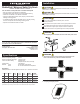
5. Apply voltage label and circuit labels.
6. Make connections as per diagram below.
a. Connect + 12V DC or 24V DC to the 12 AWG wire supply harness (Bus). Use adequate
gauge supply wire and circuit protection for safe operation up to Panel Cumulative Rating.
b. Connect positive side of each appliance to a switch output terminal. Connect
the negative side to DC negative.
COVER
PANEL
GASKET
VOLTAGE LABEL
CIRCUIT LABEL
7. Check that toggle switch boots are securely tightened.
8. Mount panel in cutout with provided gasket and screws.
4. To remove cover, apply heal of hand to label area and pull back on the
cover edge.
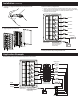
Application Example
OUT TO DEVICE
OUT TO DEVICE
OUT TO DEVICE
OUT TO DEVICE
OUT TO DEVICE
FUSE OR
CIRCUIT BREAKER
WIRE HARNESS (BUS)
FUSE OR
CIRCUIT BREAKER
FUSE OR
CIRCUIT BREAKER
FUSE OR
CIRCUIT BREAKER
FUSE OR
CIRCUIT BREAKER
FUSE OR
CIRCUIT BREAKER
EXAMPLE DEVICE
PN 4307 shown for
illustration purposes
VHF
Connect adequate gauge supply
wire and circuit protection for
safe operation up to Panel
Cumulative Rating.
FUSE
PN 5035
ST-BLADE FUSE BLOCK
6 INDEPENDENT CIRCUITS
WIRE HARNESS (BUS)
PN 4307 shown for
illustration purposes
VHF
BILGE PUMP
FISH FINDER
STEREO
HORN
GPS
EXAMPLE DEVICES
Connect adequate gauge
supply wire and circuit protection
for safe operation up to Panel
Cumulative Rating.
Legend
DC Positive
DC Negative
FUSE
COMMON BUSBAR
WeatherDeck® Switch Only Panel with ST-Blade Independent Circuit Fuse Block