
Owner's manual

3. AC Meter Terminals
There are two terminals on the back of the meter marked “+” and “-”. On DC meters these
markings refer to positive and negative. On AC meters these markings can be disregarded.
Functionally it will not matter to which terminal the coil wires are connected.
4. Install Ammeter Coil
Route the AC hot lead to be measured through the center of the sensing coil. Connect the
sensing coil wires to the meter. Secure the sensing coil to the hot lead to prevent it from moving.
If needed, the sensing coil wires may be lengthened up to 50 feet (15.24m) using 16 AWG wire.
5. Calibration
The ammeter is calibrated at the factory and recalibration should never be necessary. However,
if adjustment does become necessary the needle may be reset to the zero mark.
In the center of the black area on the meter front is an adjustment screw. This screw activates a
small cam that defl ects the meter needle slightly to adjust the needle position.
Using a small screw driver, turn the screw no more than 90 degrees right or left, as necessary.
DO NOT ROTATE THE ADJUSTMENT SCREW THROUGH 360 DEGREES.
(
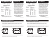
Installation (continued)
PN 8246 PN 8258 / PN 9630 Surface Mount Panel Mount
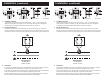
Wiring Diagram
AC Ammeters
PN 8258 / PN 9630
3. AC Meter Terminals
There are two terminals on the back of the meter marked “+” and “-”. On DC meters these
markings refer to positive and negative. On AC meters these markings can be disregarded.
Functionally it will not matter to which terminal the coil wires are connected.
4. Install Ammeter Coil
Route the AC hot lead to be measured through the center of the sensing coil. Connect the
sensing coil wires to the meter. Secure the sensing coil to the hot lead to prevent it from moving.
If needed, the sensing coil wires may be lengthened up to 50 feet (15.24m) using 16 AWG wire.
5. Calibration
The ammeter is calibrated at the factory and recalibration should never be necessary. However,
if adjustment does become necessary the needle may be reset to the zero mark.
In the center of the black area on the meter front is an adjustment screw. This screw activates a
small cam that defl ects the meter needle slightly to adjust the needle position.
Using a small screw driver, turn the screw no more than 90 degrees right or left, as necessary.
DO NOT ROTATE THE ADJUSTMENT SCREW THROUGH 360 DEGREES.
(
Installation (continued)
PN 8246 PN 8258 / PN 9630 Surface Mount Panel Mount
Wiring Diagram
AC Ammeters
PN 8258 / PN 9630