
Inc. One Selector Battery Switch Installation Manual
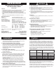

Wire Sizing Chart
1. Calculate the maximum sustained amperage of the circuit. Measure the
length of the circuit from the power source to the load and back.
2. Calculate Famps (Feet x amps). Multiplycircuit lenght by max. current.
3. Base the wire on either the 3% or 10% voltage drop. In general, items
which affect the safe operation of the boat and its passengers (running
lights, bilge blowers, electronics) use 3%; all other loads use 10%.
4. Are the circuit runs in an engine space or non engine space?
5. Starting in the Famps column with the right voltage and voltage drop,
run down the list until arriving at a value which is greater than the
calculated Famps. Move left to the Ampacity column to verify that the
total amperage of the circuit does not exceed the maximum allowable
amperage of the wire size for that row. If it does, move down until the
wire ampacity exceeds the circuit amperage. Finally, move left to the
wire size column to select the wire size.
Note: For wire with 105°C insulation rating and AWG wire sizes.
Chart courtesy of the West Advisor
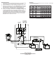
2
1
COMMON
LEDLEDLEDLED
TO 24 HOUR
CIRCUITS
TO DC HOUSE
DISTRIBUTION
PANEL OR HIGH
AMP DC LOAD
100A
OUTPUT TO
ENGINE
ALTERNATOR
OR STARTER
DC NEGATIVE
DISTRIBUTION BUS
CL-SERIES 7600
BATTERYLINK
TM
ACR
B A
HOUSE
ENGINE
Wiring Diagram
Dual Battery Main Distribution Panel
PN 8687 Shown
Example
A 12 volt system at 10% drop with a 40’ circuit x 45 amps = 1800 Famps.
A wire size of 8 is required.