E26 CONVECTION OVEN SERVICE MANUAL Revision 1/F3503 -1-
WARNING: ALL INSTALLATION AND SERVICE REPAIR WORK MUST BE CARRIED OUT BY QUALIFIED PERSONS ONLY.
CONTENTS This manual is designed to take a more in depth look at the E26 convection oven for the purpose of making the unit more understandable to service people. There are settings explained in this manual that should never require to be adjusted, but for completeness and those special cases where these settings are required to change, this manual gives a full explanation as to how, and what effects will result. SECTION PAGE NO. 1. SPECIFICATIONS .........................................................
Revision 1/F3503 -4-
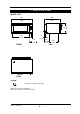
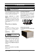
1. SPECIFICATIONS 668 (34.9) (26.3) 430 885 791 45 (31.1) (1.75) 124 179 395 (4.9) (7.0) (15.5) FRONT SIDE PLAN LEGEND - Electrical connection entry point Dimensions shown in millimetres. Dimensions in inches shown in brackets. Revision 1/F3503 -5- (16.
LOCATION To ensure correct ventilation for the motor and controls the following minimum installation clearances are to be adhered to: Rear Left-hand side Right-hand side 25mm / 1” 25mm / 1” 25mm / 1” OVEN INTERNAL DIMENSIONS Width Height Depth Oven Volume 635 mm / 25” 270 mm / 10.5” 500 mm / 19.5” 0.14 m³ / 5.0ft³ OVEN RACK SIZE Width Depth: 600 mm 400 mm ELECTRICAL SUPPLY SPECIFICATION OPTIONS 220Vac, 50/60Hz, 11A, 2.4kW @ 220V 230-240Vac, 50Hz, 10A, 2.
2. INSTALLATION WARNING: THIS APPLIANCE MUST BE GROUNDED. WARNING: ALL INSTALLATION AND SERVICE REPAIR WORK MUST BE CARRIED OUT BY QUALIFIED PERSONS ONLY. ELECTRICAL CONNECTION It is most important that the oven is installed correctly and that the operation is correct before use. Installation shall comply with local electrical, health and safety requirements. E26 convection ovens are supplied with pre-fitted cords. Ensure unit is fitted with the correct cord and plug for the installation.
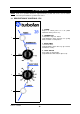
3. OPERATION NOTE: A full user’s operation manual is supplied with the product and can be used for further referencing of installation, operation and service. 3.1 DESCRIPTION OF CONTROLS - E26 1. POWER Depress to switch power on or off (switch illuminates when power is on). 2. THERMOSTAT Temperature range 50 - 250°C. Light illuminates when elements are cycling ON to maintain set temperature. 1 3. BAKE TIMER 1 Hour bake timer. (Light illuminates when “time up” (0) reached, and buzzer sounds). 4.
3.2 ‘Off’ position, the element relies on the thermostatic control to prevent it switching on. Accordingly, if the oven temperature drops below approximately 20°C the thermostat and element may cycle on at this setting. EXPLANATION OF CONTROL SYSTEM The E26 Turbofan convection ovens feature multi-function operator controls for which a correct understanding of their operation is required before carrying out any service or fault repair work.
4. MAINTENANCE WARNING: ALL INSTALLATION AND SERVICE REPAIR WORK MUST BE CARRIED OUT BY QUALIFIED PERSONS ONLY. 4.1 CLEANING OVEN SEALS To remove, hold at their centre point and pull forward until they unclip. Remove side seals first, then top and bottom. The seals may be washed in the sink, but take care not to cut or damage them. To replace, ensure that the lip is facing the oven opening. Fit the top and bottom seals first, then the side seals. WARNING: ALWAYS TURN THE POWER SUPPLY OFF BEFORE CLEANING.
5. TROUBLE SHOOTING WARNING: ALL INSTALLATION AND SERVICE REPAIR WORK MUST BE CARRIED OUT BY QUALIFIED PERSONS ONLY. FAULT THE OVEN DOES NOT OPERATE / START POSSIBLE CAUSE REMEDY The mains isolating switch on Turn on. the wall, circuit breaker or fuses are “off” at the power board. The power switch on the oven is Depress switch. Switch will off. illuminate. FAN DOESN’T OPERATE Incorrect electrical supply. (Refer fault diagnosis 6.1.1) Ensure electrical supply correct. Power switch on unit faulty.
FAULT NO HEAT POSSIBLE CAUSE REMEDY No power to thermostat. (Refer fault diagnosis 6.1.7) Identify fault and correct. Thermostat faulty. (Refer fault diagnosis 6.1.7) Replace. (Refer service section 6.3.7) Fan element faulty (Refer fault diagnosis 6.1.10) Correct element fault. (Refer Fault: Fan Element) NO TEMPERATURE CONTROL Thermostat faulty. (Refer fault diagnosis 6.1.8) Replace. (Refer service section 6.3.7) SLOW RECOVERY Overloading of oven. Reduce oven loading.
6. SERVICE PROCEDURES WARNING: ENSURE POWER SUPPLY IS SWITCHED OFF BEFORE SERVICING. WARNING: ALL INSTALLATION AND SERVICE REPAIR WORK MUST BE CARRIED OUT BY QUALIFIED PERSONS ONLY. SECTION 6.1 FAULT DIAGNOSIS.............................................................................................................. 14 6.1.1 6.1.2 6.1.3 6.1.4 6.1.5 6.1.6 6.1.7 6.1.8 6.1.9 6.1.10 6.1.11 6.2 Control Panel ...................................................................................................
6.1 FAULT DIAGNOSIS With the door closed there should be power to the com terminal and the n.o. terminal. 6.1.1 OVEN DOES NOT OPERATE / START With the door open there should be power to the com terminal and the n.c. terminal. Incorrect electrical supply If not, microswitch is faulty—replace. Check that the voltage across phase and neutral (L1 and L2) terminals of terminal block is the voltage as stated on the unit’s electrical rating plate. 6.1.
6.1.6 60 MINUTE TIMER NO TIME UP INDICATOR 6.1.10 FAN ELEMENT NOT WORKING Element faulty (blown) Indicator faulty With the thermostat on and heating check voltage across fan element terminals at rear of oven. If the voltage is correct then check the current draw of element. If there is no current draw then element is faulty—replace. With the timer in the zero position, check for voltage across the indicator light. If correct, then the indicator light is faulty—replace.
6.2 ACCESS 6.2.4 CONTROL PANEL—REAR 6.2.1 CONTROL PANEL 1) Undo one screw at bottom of control panel. Power Switch Heating Indicator Thermostat One Screw Figure 6.2.1 Bake Time Up Indicator 2) Pull out bottom of control panel and drop down to disengage tabs at top of control panel. Bake Timer 6.2.2 SERVICE (REAR) PANEL 1) Undo the four screws holding the panel. Light Switch Four Screws Buzzer Figure 6.2.2 Figure 6.2.4 2) Remove panel. 6.2.3 BAFFLE 1) Remove trays, racks and bottom tray.
6.3 REPLACEMENT Neon Wires 6.3.1 LIGHT BULB / GLASS 1) Unscrew lamp cover. Lamp Cover Figure 6.3.3 2) From back push neon through front of panel rotating clockwise. 3) Push new neon in from front of panel, and reconnect wires. 6.3.4 POWER / LIGHT SWITCHES Figure 6.3.1 2) Unscrew bulb out of fitting. 1) With control panel open (refer 6.2.1) remove the wires from the back of the switch, noting their positions. 3) Screw in replacement bulb. 4) Replace lamp cover Switch Wires 6.3.
6.3.6 BAKE TIMER 5) Withdraw old thermostat phial through rear of oven. 1) Remove bake timer knob by pulling it firmly away from control panel. 6) Insert new thermostat. 7) Re-assemble in reverse order. 2) Open control panel (refer 6.2.1) and undo two screws securing timer. 6.3.8 ELEMENT 1) With service panel and baffle removed (refer 6.2.2 and 6.2.3) remove the wires from the element. Two Screws 2) Unscrew the element from inside the oven. Figure 6.3.6 3) Transfer wires to new timer.
Hinge Locking Notch 6.3.10 MOTOR 1) Remove fan (refer 6.3.9), remove service panel (refer 6.2.2), and then remove the wires that go to the motor. 2) Undo the four screws holding the motor bracket in place (from the outside) and remove motor assembly. Hinge Locking Clip Figure 6.3.13 Phase Terminal Neutral 3) Lift door away from the oven and place on a flat surface. Screws (4) Earth / Ground 4) Undo three screws and remove the trim from the bottom of the door. Carefully withdraw the glass. Figure 6.
3) Uncrimp the retaining lugs of the window spacer and remove the spacer and glass. 6.3.15 DOOR HINGES 1) Remove outer glass (refer 6.3.12). 2) Undo two screws securing hinge assembly to oven door. Retaining Lugs Two Screws Figure 6.3.18 Figure 6.3.16 3) Withdraw hinge assembly and replace. Reassemble in reverse order. 4) To replace, ensure the silicone rubber seal has not been displaced. Clean the glass and refit it.
6) Remove three screws securing lintel support to oven and remove. Three screws Two screws Figure 6.3.24 11) Replace, ensuring roller to top of bracket. Re-assemble in reverse order. Figure 6.3.21 7) Remove wrapper. 8) Undo two screws securing left hand counter bracket to oven and remove. Replace, ensuring that bracket is installed with roller to top. Two screws Figure 6.3.22 9) Remove two screws securing insulation panel to oven liner. Two Screws Insulation panel Figure 6.3.
6.4 ADJUSTMENT / CALIBRATION 6.4.1 THERMOSTAT CALIBRATION - E25 IMPORTANT: IF THE OVEN TEMPERATURE NEEDS TO BE INCREASED, ENSURE THAT THE THERMOSTAT IS IN THE ‘OFF’ POSITION BEFORE CARRYING OUT ADJUSTMENT. IF OVEN TEMPERATURE NEEDS TO BE DECREASED, ENSURE THERMOSTAT IS IN THE ‘MAX’ TEMPERATURE POSITION BEFORE CARRYING OUT ANY ADJUSTMENT. Actuator Arm Figure 6.4.2 6.4.3 60 MINUTE TIMER ZERO POSITION ADJUSTMENT 1) Remove 60 minute timer knob by pulling it firmly away from control panel. 1) Turn off power.
7. ELECTRICAL CIRCUIT SCHEMATIC FAN ELEMENT 220v 2.4Kw 240V 2.
8.
9.
10.
11. PARTS DIAGRAMS 11.
Pos Part No.
11.2 CONTROL PANEL ASSEMBLY - E26 Pos 22 22 51 52 53 54 55 56 57 58 Part No.
11.
UNITED KINGDOM Units 6-7 Mount St Business Park Birmingham B7 5QU England Tel 0121-327 5575 Fax 0121-327 9711 UNITED STATES OF AMERICA 1-35 Business Center Building 1 12000 Crown Point Drive, Suite 100 San Antonio, Texas 78233 Tel 1-800-551 8795 Fax 210-590 9479 NATIONAL COVERAGE FOR SERVICE OR MAINTENANCE DIAL FREE CALL 1800 551 8795 (USA ONLY) Revision 1/F3503 -31-