INSTALLATION AND OPERATION MANUAL GAS TARGET TOP RANGE / ELECTRIC OVENS GE570 / GE576 232433-7
MANUFACTURED BY Moffat Limited Christchurch New Zealand INTERNATIONAL CONTACTS AUSTRALIA Moffat Pty Limited E.Mail: Main Office: Service: Spares: Customer Service: vsales@moffat.com.au (tel): +61 (03) 9518 3888 (fax): +61 (03 9518 3833 (tel): 1800 622 216 (tel): 1800 337 963 (tel): 1800 335 315 (fax): 1800 350 281 CANADA Serve Canada Web: E.Mail: Sales: Service: www.servecanada.com info@servecanada.com (tel): 800 551 8795 (Toll Free) (tel): 800 263 1455 (Toll Free) NEW ZEALAND Moffat Limited Web: E.
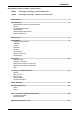
Contents Blue Seal Gas Target Top Range / Electric Ovens GE570 Gas Target Top Range / Electric Static Oven. GE576 Gas Target Top Range / Electric Convection Oven. Introduction .............................................................................................. 2 Specification ..............................................................................................
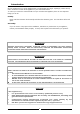
Introduction We are confident that you will be delighted with your BLUE SEAL Gas Target Top Range / Electric Ovens, and it will become a most valued appliance in your commercial kitchen. To ensure you receive the utmost benefit from your new Blue Seal appliance, there are two important things you can do. Firstly: Please read the instruction book carefully and follow the directions given. The time taken will be well spent.
Specifications Model Numbers Covered in this Specification GE570 Gas Target Top Range / Electric Static Oven - 900mm. GE576 Gas Target Top Range / Electric Convection Oven - 900mm. General A commercial heavy duty, gas fired Target Top having a high output, two stage double-ring iron cast burner offering accurate temperature control and infinitely variable heat with the heat radiating out from the centre of the Target Top. The Main Burner is located underneath removable cast target top plates.
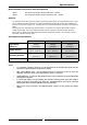
Specifications Gas Connection Gas supply connection point is located at the rear of the appliance, approximately 130mm from the right hand side, 32mm from the rear and 655mm from the floor and is reached from beneath the appliance. An optional underside connection is available. (Refer to the ‘Dimensions’ section). Connection is ¾" BSP male thread. Electrical Supply Requirements 1-Phase Connection 1P+N+E 230-240V MODEL 3-Phase Connection 3P+N+E 400-415V GE570 6.5kW, 26.6 Amps @ 235V 6.5kW L1 - 8.
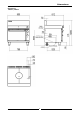
Dimensions Dimensions GE570 / GE576 5
Installation Installation Requirements NOTE: • It is most important that this appliance is installed correctly and that operation is correct before use. Installation shall comply with local gas, electrical and health and safety requirements. • This appliance shall be installed with sufficient ventilation to prevent the occurrence of unacceptable concentrations of health harmful substances in the room, the appliance is installed in.
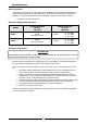
Installation Clearances NOTE: Only non-combustible materials can be used in close proximity to this appliance. Combustible Surface Non Combustible Surface Left / Right hand side 50mm 0mm Rear 50mm 0mm * Side clearances can be 50mm when the adjacent surface is at least 100mm below the cooking surface. Assembly NOTE: • All Models are delivered completely assembled. No further assembly is required. Refer to the information below for assembly instructions.
Installation NOTE: • The burner operating pressure is to be measured at the manifold test point with the main burner operating at the 'High Flame' setting. • NAT, LPG & Butane Only - The operating pressure is ex-factory set and is not to be adjusted, apart from when converting between gasses, if required. • Refer to the ‘Gas Conversion and Specifications' section of this manual for further details. The regulator connections are 3/4" BSP female. The connection to the appliance is 3/4" BSP male.
Installation C AUTIO N : Changing the supply from 3 phase to single phase will increase the electrical current loading on the supply cable. Ensure that the supply cable used is of a sufficient size for the current loading, refer to the 'Electrical Supply Requirements' table overleaf. 5. 6. 7. 8. Connect neutral and earth conductors to neutral stud and earth stud respectively. For all connections ensure that conductors are secure and appropriately terminated.
Operation Operation Guide C AUTIO N : • This appliance is for professional use and is only to be used by qualified people. • Only authorised service persons should be used to carry out installation, servicing or gas conversion operations. • Components having adjustments protected (e.g. paint sealed) manufacturer should not be adjusted by the user / operator. 1. 2. by the Blue Seal appliances have been designed to provide simplicity of operation and 100% safety protection.
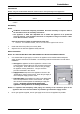
Operation Lighting the Pilot Burner (Target Top) 1. Remove centre casting with the casting removal tool. 2. Depress the control knob and rotate anti-clockwise to the ‘PILOT’ position. 3. With the control knob depressed, manually light the pilot burner located in front of the main burner. 4. Hold in the control knob for approximately 10 to 15 seconds, then release. 5. The pilot burner should remain alight. If not repeat Items 2 to 4 above until the pilot burner lights.
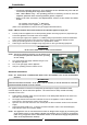
Operation Oven ! IMPORTANT DO NOT USE aluminium foil or trays directly on the cast iron sole plate(s). NEVER block or cover the openings on each side of the sole plate(s). The oven is fitted with top and bottom elements. The thermostat maintains the overall oven temperature. The top element is further controlled by the oven top heat control. Convection Ovens (GE570 / GE576) are fitted with a circulation fan.
Cleaning and Maintenance C AUTIO N : Always turn ‘Off’ the electrical and gas supply before cleaning. This appliance is not water proof. Do not use water jet spray to clean interior or exterior of this appliance. General Clean the Target Top / Range regularly. A clean appliance looks better, will last longer and will perform better. Carbonised grease on the cooking surface will hinder the transfer of heat from the cooking surface to the food. This will result in loss of cooking efficiency.
Cleaning and Maintenance Target Top a. This should be kept clean of any build up of spillage’s of food. Provided the cast iron work surface is regularly used it will maintain itself in good condition with no special cleaning requirements being necessary. b. Clean any food residue and spillage from the channels around the centre casting and main plates before use. c. DO NOT use water on the castings while they are still hot as cracking may occur.
Fault Finding This section provides an easy reference guide to the more common problems that may occur during the operation of your appliance. The fault finding guide in this section is intended to help you correct, or at least accurately diagnose problems with your equipment. Although this section covers the most common problems reported, you may encounter a problem not covered in this section.
Wiring Schematic Static Oven (GE570) 16
Wiring Schematic Static Oven Wiring Diagram (GE570) 17
Wiring Schematic Convection Oven (GE576) 18
Wiring Schematic Convection Oven Wiring Diagram (GE576) 19
Gas Conversion and Specifications Conversion Procedure C AUTIO N : Ensure that the appliance is isolated from the gas supply before commencing servicing. NOTE: • These conversions should only be carried out by qualified persons. All connections must be checked for leaks before re-commissioning the appliance. • For all relevant gas specifications refer to the ‘Specifications’ table at the end of this section. Main Burner 1. 2. 3. 4. 5. 6. 7. Remove the control knob from the front control panel.
Gas Conversion and Specifications Pilot Burner 1. 2. 3. 4. 5. 6. To remove the pilot burner, disconnect the gas supply tube from the base of the pilot burner. Remove the bolt securing the retaining plate holding the pilot burner and thermo couple to the mounting bracket. Remove the retaining plate. The pilot burner can now be removed from the mounting bracket. Unscrew the base nut from the pilot burner and withdraw injector and spring from inside the pilot burner.
Gas Conversion and Specifications Gas Regulator - NAT Gas / LPG / Butane Only. NOTE, Pin rotated for Natural Gas NOTE, Pin rotated for LPG Fig 16 NOTE: The regulator supplied is convertible between Natural Gas and LP Gas, but it’s outlet pressure is fixed ex-factory and is NOT to be adjusted. 1. 2. 3. 4. Ensure that the gas supply is turned 'Off' at the mains. Unscrew the hexagonal cap (23mm A/F) from the regulator.
Gas Conversion and Specifications Gas Type Identification Label On completion of the gas conversion, replace gas type identification label, located:- At the rear of the unit, above the gas connection. - Beside the Rating Plate. Commissioning Before leaving the converted installation; 1. Check all gas connections for leakages using soapy water or other gas detecting equipment. WARNING: DO NOT USE A NAKED FLAME 2. TO CHECK FOR GAS LEAKAGES.
Gas Conversion and Specifications Gas Specifications Natural Gas LP Gas Butane Town Gas (**) Main Burner Injector (Inner Ring) Ø 1.70 mm Ø 1.10 mm Ø 1.00 mm Ø 4.20 mm Main Burner Injector (Outer Ring) Ø 2.60 mm Ø 1.55 mm Ø 1.45 mm Ø 6.30 mm 0.35 0.25 0.70 Burner Aeration Screw X (Inner) 25 mm 25 mm 20 mm Burner Aeration Screw Y (Outer) 28 mm 28 mm 22 mm 21/2 turns out (ccw) 1 turn out (ccw) Blank 1½ turns out (ccw) 1.0kPa (*) 2.6kPa (*) 0.
Replacement Parts List Replacement Parts List IMPORTANT: Only genuine authorized replacement parts should be used for the servicing and repair of this appliance. The instructions supplied with the parts should be followed when replacing components. For further information and servicing instructions, contact your nearest authorized service branch (contact details are as shown on the reverse of the front cover of this manual).
Replacement Parts List General 227012 227013 014997 227892 227893 227896 228571 227963 228922 227850 229674 Centre Casting. Half Plate Casting. Casting Removal Tool. Side Rack LH. Side Rack RH. Oven Rack. Index Mark Moulding. Neon Orange. Neon White. Adjustable Leg - 150mm. Rear Roller Assy. Accessories 228800 Ranges 900mm Plinth Kit. Gas Regulator Gas Type Gas Regulators Part No. Description Nat. Gas LPG Butane 228531 ¾” BSP F/F Convertible. Town Gas 230185 ¾” BSP F/F Adjustable.
27