
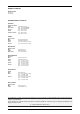
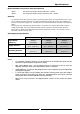
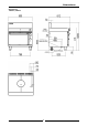
Specifications

8
NOTE:
• The burner operating pressure is to be measured at the manifold test point with the
main burner operating at the 'High Flame' setting.
• NAT, LPG & Butane Only - The operating pressure is ex-factory set and is not to be
adjusted, apart from when converting between gasses, if required.
• Refer to the ‘Gas Conversion and Specifications' section of this manual for further
details.
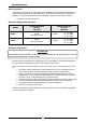
The regulator connections are
3
/
4
" BSP female.
The connection to the appliance is
3
/
4
" BSP male.
(Refer to the 'Specifications' section for the gas supply location dimensions).
NOTE: A Manual Isolation Valve must be fitted to the individual appliance supply line.
3. Correctly locate the appliance into its final operating position and using a spirit level, adjust the legs
so that the appliance is level and at the correct height.
4. Connect the gas supply to the appliance. A suitable joining compound which resists the breakdown
action of LPG must be used on every gas line connection, unless compression fittings are used.
5. Check gas operating pressure is as shown in the 'Specifications' section.
6. Check all gas connections for leakages using soapy water or other gas detecting equipment.
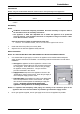
NOTE: The burner operating pressure is to be measured at
the manifold test point with both burners operating
at ‘Full’ setting.
7. Turn off the mains gas supply and bleed the gas out of
the appliance gas lines.
8. Turn on the gas supply and the appliance.
9. Verify the operating pressure remains correct.
Electrical Connection
NOTE: ALL ELECTRICAL CONNECTIONS MUST ONLY BE CARRIED OUT BY AN AUTHORISED
PERSON.
Each appliance should be connected to an adequately protected power supply and isolation switch
mounted adjacent to, but not behind the appliance. This switch must be clearly marked and readily
accessible in case of fire.
1. Check that the electricity supply is correct as shown on the Rating Plate attached to the lower front
hand side of the front sill panel.
2. The supply terminal connections are located at the rear of the appliance. Refer to ‘Electrical
Connections’ in the ‘Dimensions’ section of the manual.
3. Open the oven door and remove the oven control panel to allow connection access for the electrical
supply.
4. Connect the mains supply to L1, L2 and L3 connection terminals. Refer to the 'Electrical Supply
Requirements' section for connection details.
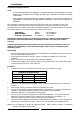
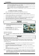
NOTE: This appliance can be converted from 3 Phase to Single Phase supply by connecting the
single phase input to L1 and adding a bridge wire between the L1, L2 and L3 connections,
(refer to Fig 3 opposite and the information shown in the 'Electrical Supply Requirements
Table' in the 'Specifications' Section).
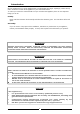
Installation
WARNING:
D
O NOT USE A NAKED FLAME TO CHECK FOR GAS LEAKAGES.
Fig 2
Manifold Test
Point
WARNING:
T
HIS APPLIANCE MUST BE EARTHED. IF THE SUPPLY CORD IS DAMAGED, IT MUST BE REPLACED BY A SUITABLY
QUALIFIED PERSON IN ORDER TO AVOID A HAZARD.