
User guide

Page 3 of 4
Nominal Battery Voltage
Minimum Dump Load Resistor
3024’s Auxiliary Output
20 Amp Maximum
Minimum Dump Load Resistor
CBM4070
40 Amp Maximum
12V
V
BAT-MAX
= 15V
0.750 Ω 0.375 Ω
24V
V
BAT-MAX
= 30V
1.500 Ω 0.750 Ω
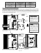
Dump Load and optional Current Booster Module wiring
The 3024 can directly drive dump loads up to 20 amps. For dump loads of up to 40 amps the optional the Current Booster Module
(CBM) part number CBM4070 may be used. The CBM consists of a large optically isolated MOSFET output stage which turns on when
a 3 to 32VDC drive signal is present on it’s input. The 3024’s 2A-CHG output is used as the PWM drive signal for the CBM. For dump
load needs in excess of 40 amps multiple CBM’s may be driven from a single 3024. For these applications multiple CBM inputs are
connected in parallel. CBM outputs must connect to separate 40 amp maximum dump loads with separate 50 amp maximum over
current protection. Do not directly parallel outputs.
Dip #4 select becomes:
OFF = Min-Power Mode
ON = Max-Power Mode
25 amp max over
current protection
Dump Load
20 amp max
Dump Load
40 amp max
Connect to 20A LOAD terminal.
50 amp max over
current protection
Connect CBM4070 to
2A CHG terminal. This
3024 output provides
internal 2 amp over
current protection
Current Booster Module
CBM4070
3024 directly driving dump
load up to 20 amps
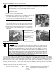
¾ WARNING: Current Booster
Module part number CBM4070
must be mounted with heatsink
fins oriented vertically as shown
to facilitate convection cooling.
Do not separate power module
from heatsink, enclose in a
confined space or restrict air
flow. Do not connect the input or
output reverse polarity or exceed
the 40 amp PWM current rating.
3024 driving dump load up to 40 amps with
optional Current Booster Module p/n CBM4070
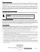
¾ Generator Connection: The
wind/hydroelectric generator con-
nects directly to the battery and
is intentionally omitted in this
wiring diagram so as to not
preempt the generator manufac-
turers installation and safety
instructions.