OWNER’S MANUAL BatteryPlus35-II BatteryPlus35-II-HA BatteryPlus35-II-SI BatteryPlus35-II-SR TEAMBMPRO.
MANUAL PART 035632 REV 5.0 Copyright © 2020 Designed by BMPRO, one of Australia’s leading power solution experts, the BMPRO range of products are proudly Australian-Made in Melbourne, Victoria and represent a high-quality product that will provide years of service. DISCLAIMER: BMPRO accepts no liability for any loss or damage which may occur from the improper or unsafe use of its products. Warranty is only valid if the unit has not been modified or misused by the customer.
POWERING YOUR ADVENTURES With over 50 years’ experience in power solutions combined with manufacturing and design facilities in Melbourne, Australia, BMPRO are the leading experts in RV power management. Inspired by the great outdoors, we have created a range of rugged, smart and reliable products to power your adventures.
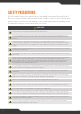
SAFETY PRECAUTIONS Please read the Safety Precautions before installing or using the BatteryPlus35-II. Be sure to observe all precautions without fail. Failure to observe these instructions properly may result in personal damage, or personal injury which depending on the circumstances may be serious and cause loss of life. WARNING Ensure that there is a good ventilation from the battery area. Correct installation is the most critical factor in ensuring the safe use of the BatteryPlus35-II.
WARNING CAUTION: Risk of fire. Do not replace any vehicle fuse with a rating higher than recommended by the vehicle manufacturer. This product is rated to draw between 20 and 30 amperes from a 12V vehicle outlet, depending on your model of BatteryPlus35-II. Ensure that the electrical system in your vehicle can supply this product without causing the vehicle fusing to open.
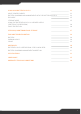
CONTENTS 6 SAFETY PRECAUTIONS IMPORTANT SAFETY INSTRUCTIONS 4 5 ABOUT THE BATTERYPLUS35-II OPTIONAL ADD-ONS COMPATIBLE BATTERY TYPES 8 8 9 DESCRIPTION OF PARTS 10 INSTALLATION INSTRUCTIONS PERSONNEL EARTHING SIMPLE WIRING DIAGRAM WIRING DIAGRAM WITH OPTIONS VENTILATION, ORIENTATION AND THERMAL CONSIDERATIONS MOUNTING MAINS CABLE LOAD, BATTERY AND EXTERNAL DC INPUT CONNECTIONS MAIN CHARGE CONNECTION CARAVAN BATTERY CONNECTION REPLACING BATTERIES 13 13 13 14 15 16 17 17 18 19 19 20
USING YOUR BATTERYPLUS35-II INPUT POWER SOURCES BATTERY CHARGING AND MANAGEMENT WITH THE BATTERYPLUS35-II ECO MODE STORAGE MODE USING THE BATTERYPLUS35-II AS A POWER SUPPLY (BATTERYLESS OPERATION) FAULT PROTECTION 22 22 24 25 25 SERVICING, MAINTENANCE AND STORAGE 27 FAQS AND TROUBLESHOOTING BATTERY CARAVAN LOADS SOLAR 28 28 28 29 APPENDICES BATTERYPLUS35-II OPERATIONAL STATUS INDICATOR BATTERY CHARGING MANAGEMENT ALGORITHM 30 30 31 SPECIFICATIONS 33 COMPLIANCE 35 WARRANTY TERMS AND CONDITIONS 3
ABOUT THE BATTERYPLUS35-II BMPRO’s BatteryPlus35-II is a battery management system designed specifically for use in recreational vehicles. The BatteryPlus35-II operates from 100 to 240V AC mains power supply, towing vehicle auxiliary and solar panel to provide 35A of current to simultaneously power caravan loads and charge the caravan battery. The BatteryPlus35-II is available in a range of models to suite any RV and battery management needs.
COMPATIBLE BATTERY TYPES The BatteryPlus35-II is rated to charge battery banks of up to 600Ah in capacity and of the following battery types: BATTERY Lead Acid Lithium SI SR HA* Valve-Regulated (VRLA) Yes Yes Yes Absorbed Glass Mat (AGM) Yes Yes Yes Gel Yes Yes Yes LiFePO4 No No Yes Table 2: Batteries compatible for use with the BatteryPlus35-II * By default, the BP35-II-HA is configured to charge lead acid batteries.
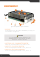
DESCRIPTION OF PARTS Figure 1: BatteryPlus35-II. Compatible for all models 1. MAINS CABLE The BatteryPlus35-II is pre-cabled with a permanent mains power supply cord for use with 240V or 110V input power. WARNING Do not replace a damaged power supply cord. If the power cord is damaged, the BatteryPlus35-II must be discarded. Ensure that the AC mains source always has an earth terminal. 2. LOAD TERMINAL BLOCK – COMMON NEGATIVE CONNECTION Negative wire connection return point for the caravan’s 12V loads.
Terminals are labelled according to their designated load output TERMINAL OUTPUTS LOAD RATING 1 Tablet / Spare 15A 2 Spare 15A 3-9 Spare 10A 10 Light 1 10A 11 Light 2 10A 12 Light 3 10A 13 Pump 1 10A 14 Pump 2 10A Table 3: Designated terminal-load outputs 5. AUX+ Connection point for external DC input positive. 6. BATT+ Connection point for battery positive and negative terminal. Attach fuse to Batt+ wiring 7. BATT8. NOT USED 9.
. MOUNTING HOLE (X4) 13. LOAD OUTPUT STATUS INDICATORS LED COLOUR LOAD OPERATIONAL STATUS GREEN Loads operating normally RED Fault with load OFF Load is off Table 4: LED Status Indicators 14. SOLAR PANEL CONNECTION This connection is for the solar panel input 15. +BRK BATTERY OUTPUT (40A MATCH RATED) WARNING Loads connected to +BRK output will not turn off even during ECO mode or Storage mode. To maintain good health of the battery during low voltage, manually turn these loads off.
INSTALLATION INSTRUCTIONS PERSONNEL Installation is to be carried out only by suitably qualified personnel. EARTHING As the BP35-11 is positive sensing for current monitoring, this allows for chassis earthing of both the battery and the negative of DC 12 V appliances. Note: All DC 12 V positive cables must be wired to outputs 1-14 or the 40A battery output connection.
Stereo Memory Heaters BRK+ 40A Max Fuse 40A Max Fuse 40A Max Fuse Positive Output Lights, Pump etc Negative Output AUX+ BRK+ Unregulated RV Solar Panels 18-25V BATT+ BATT- Auxiliary with Isolation Relay Solar- Solar+ SIMPLE WIRING DIAGRAM
Unregulated RV Solar Panels 18-25V SwayControl Stereo Memory Heaters BRK+ Odyssey TrailSafe Solar- Solar+ 40A Max Fuse BATT+ MiniBoost Pro (only with BC300 connected) 40A Max Fuse 40A Max Fuse Positive Output Pin 1 Lights, Pump etc Negative Output Inverter 40A Max Fuse AC AUX+ BRK+ RVView BATT+ Trek Isolation Relay MiniBoost AUX+ BATT- OdysseyLink Battery Monitors: CAN BUS WIRING DIAGRAM WITH OPTIONS 15
VENTILATION, ORIENTATION AND THERMAL CONSIDERATIONS The preferred orientation is with the load connection at the bottom, as shown in figure 2: Recommended mounting holes and located such that there is a minimum of 80 mm free air space from all vented sides of BatteryPlus35-II. This allows for the lowest operating temperature of the internal electronics and the highest reliability of the product.
MOUNTING BatteryPlus35-II should be securely mounted to a suitably rigid surface, using four pre-drilled mounting holes. Dimensions are provided in Figure 3: Mounting Diagram. Figure 2: Mounting Diagram MAINS CABLE WARNING If the supply cord is damaged, it must not be replaced and the appliance should be scrapped. This is pre-cabled and fitted with a mains plug.
Wire Size DC cables must be sized to carry the maximum full load current and to not exceed the system volt drop requirements. The following cable sizes are recommended. When running wires, if they pass through panels or wall, ensure the wires are protected from damage by sharp edges. The use of cable glands is recommended. CURRENT MINIMUM WIRE SIZE 0-10A 1.0mm2 or 18 AWG 10-20A 3.0mm2 or 14 AWG 20-30A 5.
MAIN CHARGE CONNECTION The following inputs / outputs require fork type connections: Aux+ / Batt+ / Batt- / BRK+ Max. 8.2mm Min. 3.6mm Figure 4: Fork Terminal Dimensions CARAVAN BATTERY CONNECTION WARNING A fuse must be installed in the positive connection of the battery. This fuse MUST be as close as possible to the battery. This fuse protects against short circuits and reverse battery conditions. A fuse rating no greater than 40 Amps must be used.
REPLACING BATTERIES WARNING Before using a battery other than that which was installed at the caravan dealership, consult with the battery manufacturer for a detailed description of the installation, uses and maintenance of the battery. Verify that the type and capacity of the battery or batteries used are compatible for use with the BatteryPlus35-II. Figure 4 details connection of the caravan battery to the BatteryPlus35-II.
Disconnecting a Battery from the BatteryPlus35-II 1. Power off all loads connected to the BatteryPlus35-II, the easiest way is with the switch connected to the BatteryPlus35-II’s RSW input 2. Turn off and remove all power sources (auxiliary/mains/solar) to the BatteryPlus35-II 3. Disconnect the battery’s negative (black) terminal from the BatteryPlus35-II Batt- Connection Point 4.
USING YOUR BATTERYPLUS35-II INPUT POWER SOURCES The BatteryPlus35-II can charge from auxiliary, mains and solar input sources. When multiple inputs are available to the BatteryPlus35-II, the BatteryPlus35-II uses power as specified in the tables below to provide the current to simultaneously power caravan loads and charge the caravan battery.
Auxiliary WARNING To prevent your car battery from discharging when the vehicle’s ignition is off, please ensure the auxiliary is wired so that it is automatically disconnected in this condition The auxiliary input is designed for use with 12V DC power sources. The voltage of the DC power source connected to the auxiliary input must not exceed 14.8V. Fuse protection is required at the auxiliary’s positive input and to protect the wiring from the source.
BATTERY CHARGING AND MANAGEMENT WITH THE BATTERYPLUS35-II WARNING Do not attempt to charge non-rechargeable batteries. Charging a nonrechargeable battery may result in the battery catching fire or possible explosion. The BatteryPlus35-II can deliver up to 35A to simultaneously power loads and charge the caravan battery, with a maximum charging current of 20A for the BP35-II-SI and BP35-II-SR and 30A for the BP35-II-HA with the difference being reserved to supply 12 V loads.
Battery Health Preservation The BatteryPlus35-II preserves battery health by preventing the battery from excessive discharge. The BatteryPlus35-II will start a two-stage shutdown or Low Voltage Disconnect (LVD), powering down the BatteryPlus35-II outputs. This is to conserve remaining battery capacity until the battery can be charged. LVD MODE LEAD ACID LIFEPO4 (HA ONLY) ECO 10.5V 12.0V Storage 9.8V 11.5V Recovery 12.8V 13.
Heavily Discharged Batteries (Lead Acid) The BatteryPlus35-II is will not charge heavily discharged lead acid batteries. In normal use, and with the BatteryPlus35-II battery health preservation, batteries should never become heavily discharged. If your battery is heavily discharged, disconnect if from the BatteryPlus35-II and charge with a stand-alone charger. Reconnect the battery once the battery voltage has recovered to normal levels.
Over-Temperature, Over-Voltage and Short Circuit Overload Protection The BatteryPlus35-II provides automatic protection for over-temperature, overvoltage and short circuit overload situations. If any of these situations are detected, the BatteryPlus35-II will shut down and automatically attempt a restart every 30 seconds until the fault is removed. SERVICING, MAINTENANCE AND STORAGE SERVICING This BatteryPlus35-II contains hazardous voltages and energy hazards that may cause death or injury.
FAQS AND TROUBLESHOOTING Need more help troubleshooting your BatteryPlus35-II? Contact our customer service team online at teambmpro.com/technical-support or check out our how-to videos on our YouTube channel at youtube.com/c/bmproau BATTERY I’ve fitted a battery to the BatteryPlus35-II, but it’s not detected by my BMPRO battery monitor? Check the following: 1. Battery connections are tight and not loose or corroded. 2. Battery polarity, red lead-positive, black lead-negative. 3.
None of my loads appear to be powered and the screen on my battery monitor has turned off? All loads, including any battery monitor in use with the BatteryPlus35-II will power down if the BatteryPlus35-II was put into Storage Mode. The BatteryPlus35-II will be put into Storage Mode if: 1. The user activated the switch connected to the BatteryPlus35-II RSW input. This turns off power to all caravan loads and accessories connected to the BatteryPlus35-II CAN bus such as your battery monitor.
APPENDICES BATTERYPLUS35-II OPERATIONAL STATUS INDICATOR Table 6 displays the operational status of the BatteryPlus35-II, as shown by the coloured flash of the LED Status Indicator on the BatteryPlus35-II.
BATTERY CHARGING MANAGEMENT ALGORITHM The following describes the Battery Charging Management Algorithm used by the BatteryPlus35-II when charging the caravan battery from a mains power source and by the BatteryPlus35-II-HA and BatteryPlus35-II-SR with solar charging. The BatteryPlus35-II will operate as described when the caravan loads are connected directly to the BatteryPlus35-II and not the caravan battery.
VOLTAGE LIMIT (V) CHARGE MODE CURRENT LIMIT (A) LEAD ACID LIFEPO4 SI SR HA Soft Start 12.3 12.3 10 10 10 Bulk 14.4 14.6 20 20 30 Absorption 14.4 14.6 20 20 30 Float 13.6 13.6 10 10 10 Table 10: Battery charging management algorithm voltages and currents The BatteryPlus35-II intelligently controlled charging algorithm, automatically sets charging parameters so that the caravan battery will maintain the best state of health.
SPECIFICATIONS BP35-SI Input Voltage Range BP35-SR 110-240V AC ± 10%, 50-60Hz (AU) 100 - 120V AC, 60Hz (US) Input Surge Output Current Factory Set Voltage < 40A (cold start) 35A (Load + Battery Current) 13.65V (Float Voltage) Output Ripple Voltage Battery Current Limit <150mV max. 20A max. 20A Low Voltage Disconnect (Lead Acid) 10.5V ± 0.2V Battery Connect after LVD (Lead Acid) 12.8V ± 0.2V Low Voltage Disconnect (LiFePO4) 12.0V ± 0.2V Battery Connect after LVD (LiFePO4) 13.8V ± 0.
BP35-SI AC/DC Efficiency BP35-HA >83% Cooling Fan Solar Output Current BP35-SR Thermally Controlled max. 20A 30A (nominal) Solar Start Voltage >VBatt 17.5V Solar Input Voltage (after startup) >VBatt 15-25V Ambient Temperature Communication Dimensions Weight Standards 0-50 °C Communication bus available 327mm x 207mm x 82mm 2kg Safety: AS/NZS 60335.2.
COMPLIANCE This equipment has been tested and found to comply with the limits for a Class B digital device, pursuant to Part 15 of the FCC Rules. These limits are designed to provide reasonable protection against harmful interference in a residential installation. This equipment generates, uses and can radiate radio frequency energy and, if not installed and used in accordance with the instructions, may cause harmful interference to radio communications.
WARRANTY TERMS AND CONDITIONS Registering your BMPRO product is an important step to ensure that you receive all the benefits you are entitled to. Please visit teambmpro.com to complete the online registration form for your new product today. 1. BMPRO goods come with guarantees that cannot be excluded under Australian Consumer Law. You are entitled to a replacement or refund for major failure and for compensation for any reasonably foreseeable loss or damage.
POWERING YOUR ADVENTURES. TEAM BMPRO .COM BMPRO sales@teambmpro.com 19 Henderson Rd, Knoxfield VIC 3180 Australia teambmpro.