OWNER’S MANUAL Genius TEAMBMPRO.
POWERING YOUR ADVENTURES Born by the innovative spirit of our parent company Setec, with over 50 years’ experience in power solutions, and design and manufacturing facilities in Melbourne, we are the leading experts in RV power management. Inspired by the great Australian outdoors, we have created a range of rugged, smart and reliable products to power your adventures.
SAFETY PRECAUTIONS Please read the Safety Precautions carefully before installing the power supply. Be sure to observe all precautions without fail After completing installation, conduct a trial operation to check for faults. WARNING Failure to observe these instructions properly may result in personal injury, or loss of life. Ensure that there is good ventilation from the battery area. This appliance is not intended for use by young children or infirm persons without supervision.
CAUTION Failure to observe these instructions properly may result in property damage or personal injury, which may be serious depending on the circumstances. Refer to the installation section before operating. Correct installation is the most critical factor in ensuring the safe use of the power supply. If every consideration of these instructions has been satisfied the power supply will be safe to operate.
MANUAL PART 033930 REV 1C The BMPRO product range is proudly designed and manufactured in Melbourne, Australia, and represent a high-quality product that will power your adventures for years to come. Copyright © 2019 DISCLAIMER BMPRO accepts no liability for any loss or damage which may occur from the improper or unsafe use of its products. Warranty is only valid if the unit has not been modified or misused by the customer.
CONTENTS SAFETY PRECAUTIONS 4 ABOUT THE GENIUS-II POWER SUPPLY 8 DESCRIPTION OF PARTS 9 INSTALLING THE GENIUS-II POWER SUPPLY 10 Personnel 10 Ventilation, Orientation and Thermal Considerations 10 Mounting 10 Mains Cable 10 Load, Battery and External DC Input Connections 11 Remote Load-Isolator Switch Connection 14 Battery Connection / Disconnection Procedure 15 BATTERIES 16 Paralleling Batteries 16 Storage 17 Deeply Discharged Batteries 17 SERVICING 18 FUNCTIONAL DESCRIPTION
ABOUT THE GENIUS-II POWER SUPPLY The Genius-II has been designed for use in caravans and similar recreational vehicles, providing a DC power system with optional battery back up. The units operate from 240 Vac and provide an isolated 13.65 Vdc output at 35 A for powering the load and charging the caravan battery. All the necessary protection and operating features for the load and battery are provided.
DESCRIPTION OF PARTS Names and Functions of Parts 1 2 3 4 5 6 1 Mains Cable (permanently 1. Mains Cable connected)Connected) (Permanently 240 V input power for charging the 240V input power charging caravan batteryfor and powering loads the caravan battery and 2 Mounting Bracket powering loads 3 Illuminated Power Switch 2. Mounting 240 VBracket input power switch 3. Illuminated Power Switch 4 Load Fuses 240 V input power switch Ten fuses for the 12 V loads 5 Load 4.
INSTALLING THE GENIUS-II POWER SUPPLY PERSONNEL Installation is to be carried out only by suitable qualified personnel. VENTILATION, ORIENTATION AND THERMAL CONSIDERATIONS The preferred orientation is with the cooling fins vertical and located such that there is a minimum of 80 mm free air space above and below them. This allows for the lowest operating temperature of the internal electronics and hence the highest reliability of the product.
180 mm 138 mm Four 5mm mounting holes 328 mm 316 mm Figure 1: Mounting holes Figure 1: Mounting holes Load, Battery and External DC Input Connections LOAD, BATTERY AND EXTERNAL INPUT CONNECTIONS All DC connections should be wiredDC according to Figure 3 on page 11. All DC connections should be wired according Figure 3 can on page 13. in A block diagram of the basic internal wiring of thetoGenius-II be found A block5diagram Figure on page of 15.
Load Connections Connections Up to 10 Load independently-fused loads may be connected. Loads are attached using the two Up to 10 independently-fused loads may be 10-way terminal connected.blocks. Loads are attached using the two 10-way 3.6mm min 8.2mm max terminal blocks. Refer to Table 2 for wire size recommendations. Refer to Table 2 for wire size recommendations.
Fuse 8 10A Fuse 7 10A Fuse 6 10A Fuse 5 10A Fuse 4 10A Fuse 3 10A Fuse 2 10A Fuse 1 10A Figure 3: DC Wiring Diagram 12V Caravan Battery + The solar regulator may be connected at the Genius-II or at the caravan battery as shown above. – Figure 3: DC Wiring Diagram + Load 10 – Fuse 9 10A ........
Solar Panel Connection CAUTION Solar panels should not be directly connected; a solar panel voltage regulator must be fitted between solar panels and the battery. Solar power should (through a series voltage regulator) be connected directly into the caravan battery circuit. See Figure 3 on page 9. The solar power may be wired directly to the caravan battery, or to the caravan battery connections on the Genius-II. Use whichever connection point is most convenient from a wiring perspective.
BATTERY CONNECTION/DISCONNECTION PROCEDURE WARNING Sparks have the potential to cause an explosion should combustible gases be present. The following procedures are designed to minimise the risk of spark generation while connecting or disconnecting the battery. Battery Connection Procedure The caravan battery should be connected as per the following steps. 1. Remove mains power to the Genius-II Turn off the power switch on the Genius-II 2.
BATTERIES Note: This battery charger is rated to charge lead acid batteries of up to 300 Ah capacity. Charging current is limited to 15 A or 30 A depending on the type of the model. Refer to About the Genius-II Power Supply. When using batteries with this product always consult with the battery manufacturer for a detailed description of the installation, use and maintenance of the battery. (AGM) and for Gelcharging batteries.
WARNING Do not install battery in the same compartment where flammable material such as petrol is stored. STORAGE If the caravan is to be stored for a long period of time, first fully charge the battery and ensure all loads are disconnected. Recharge the battery at least once every 6 months. Regular recharging will prevent the battery from becoming deeply discharged—a condition which can significantly shorten battery life.
SERVICING This product contains hazardous voltages and energy hazards, which can result in death or injury. Only properly qualified service personnel may service it. There are no internal user serviceable parts. Only the fuses located in the exposed terminal block area are user serviceable. Isolate mains power, batteries and other DC input sources before servicing.
AC/DC POWER SUPPLY This provides an isolated 13.65 V DC output for powering of the load and charging of the battery. Battery current is sensed and monitored by the power supply to limit the charging current to 15 A or 30 A maximum depending on the model. Refer to About the Genius-II Power Supply. FAULT PROTECTION The power supply provides automatic protection for overload including short circuit, over-voltage, over-temperature and reverse connected battery.
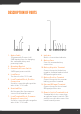
BATTERY CHARGING MANAGEMENT To maintain the battery in a good state of health, an intelligently controlled charging algorithm is used. The purpose is to ensure that the correct voltages are applied to the battery terminals at the appropriate times throughout its usage cycle. The basics of the charging algorithm are detailed in Figure 6. Charging Algorithm When mains is interrupted during Vfloat mode Vfloat (13.65V) Vboost (14.05V) Vstore (13.25V) 15 min 24 Hours Battery Voltage Vstore (13.
LED INDICATOR Indicator ALED multi-colour LED indicator is provided to indicate the following operating conditions.
SPECIFICATIONS Input Voltage 240 Vac nominal, ±10%, 50/60 Hz. The power supply will withstand a 5 min +15 % surge on the maximum nominal voltage Input Surge < 40 A (cold start) Holdup Time < 10 mS at full load current and over nominal input voltage operating range Output Current 35 A Continuous (load + battery current) Factory Set Voltage 13.65 V +/0.
WARRANTY TERMS AND CONDITIONS Registering your BMPRO product is an important step to ensure that you receive all of the benefits you are entitled to. Please visit www.teambmpro.com to complete the online registration form for your new product today. 1. BMPRO goods come with guarantees that cannot be excluded under Australian Consumer Law. You are entitled to a replacement or refund for major failure and for compensation for any reasonably foreseeable loss or damage.
POWERING YOUR ADVENTURES. TEAM BMPRO .COM BMPRO +61 3 9763 0962 | sales@teambmpro.com 19 Henderson Rd, Knoxfield VIC 3180 Australia teambmpro.