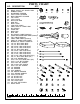
NO. DESCRIPTION 1 2 3 4 5 6 7 8 9 10 11 12 13 14 15 16 17 18 19 20 21 22 23 24 25 26 27 28 29 30 31 32 33 34 35 36 37 38 39 40 41 42 43 44 45 46 47 48 49 50 51 52 53 54 55 56 57 58 59 60 PARTS CHART QTY.
PARTS CHART NO. DESCRIPTION 61 62 63 64 65 66 67 68 69 70 71 72 73 74 75 76 77 78 79 80 81 82 83 84 85 86 87 88 89 90 91 92 93 94 95 96 97 98 99 100 101 102 103 104 105 106 107 108 109 110 111 QTY. BIG PULLEY 31 SMALL PULLEY OF SWIVEL ARM 2 RUBBER DONUT 2 ADJUSTABLE STOPPER 2 FOOT PLATE STOPPER 2 BACK BRACKET STOPPER 1 TOP PLATE 1 10 LB.
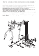
ST E P 1 ASSE M BL E M AI N FR AM E To ease the assembly process, do not tighten bolts until instructed. 1. Attach Rear Stabilizer(2) to Base Frame(1) using two 3/8"X3" Bolts(88), four 3/8" Washers(101) and two 3/8" Nuts(107). Attach Front Stabilizer(10) and Low Row Connector(13) to Base Frame(1) using two 1/2"X3" Bolts(85) and two 1/2" Nuts(106). Cap Rear Stabilizer(2) and Front Stabilizer(10) with four 50mm SQ. Caps(40). 2.
ST E P 2 ASSE MBL E PR E SS AR M & C ABL E AR M ASSE MBL Y 1. Attach Press Arm Selector(8) to Top Frame with bearing pre-installed(5) by aligning holes and inserting 19.95mm Axle(31A). Lock into place with pre-installed set screw. 2. Attach Press Arm(9) to Press Arm Selector(8) by aligning holes and inserting Pivot Axle(31). Lock into place with pre-installed set screw. 3. Attach 50mm Plugs(41) onto ends of Press Arm(9) and Press Arm Selector(8). 4.
ST E P 3 ASSE MBL E SE AT FR AME AND SE AT BAC K 1. Attach Seat Frame(11) to Front Upright(4) using two 3/8"X3" Bolts(88), four 3/8" Washers(101) and two 3/8" Nuts(107). Attach Seat Frame(11) to Base Frame(1) using 3/8"X4-1/2" Bolt(87), two 3/8" Washers(101) and one 3/8" Nut(107). 2. Attach Leg Extension Arm with bearing pre-installed(12) to Seat Frame(11) by aligning holes and then inserting Leg Extension Axle(33).
TOP CABLE 182" (4630mm) length Assemble cables and pulleys simultaneously.
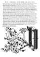
AB CRUNCH CABLE 174" (4420mm) length Route the AB Crunch Cable(78) through slot and over pulley on Front Upright(Fig 1), down to the front pulley on top of Cable Arm Assembly(Fig 2), then up to lower pulley on double pulley block(26)(Fig 3), down through the rear pulley on Cable Arm Assembly (Fig 4) to pulley on Base Frame (Fig 2), then forward toward Leg Extension Arm. Route AB Crunch Cable under both pulleys on Base Frame and under pulley on Leg Extension Arm.
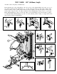
CABLE ARM CONNECTING CABLE 185" (4710mm) length Attach pulley on base frame near weight stack as shown Fig 1 with ball end of cable toward weight stack. Route cable up to low pulley of adjustable pulley block (Fig 2), then down to pulley on Base Frame (Fig 3), up to right side pulley in Top Frame (Fig 4) and thread into the Single Pulley Block( 27)(Fig 5).
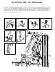
CABLE ARM CABLE 213" (5410mm) length Attach pulley and Pulley Guide Bracket(24) to Cable Arm Assembly as shown in Fig 3 and Fig 4, Be certain that, when tightened, the Pulley Guide Brackets do not interfere with the cable movement. Route Cable Arm Cable (81) around these pulleys as shown and around pulley in the Single Pulley Block (27)(Fig 5).