
Operation Manual


1
4
5
3
7
2
46
15
46
85
85
10
40
40
88
40
40
54
88
88
69
47
84
84
41
85
85
43
89
89
67
68
63
6
6
47
13
14
98
106
106
100
100
101
106
106
101
107
106
107
107
101
101
109
101
101
101
106
106
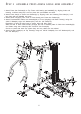
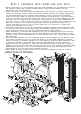
ST E P 1 A SSE M B L E M A I N F R A M E
5
To ease the assembly process, do not tighten bolts until instructed.
1. Attach Rear Stabilizer(2) to Base Frame(1) using two 3/8"X3" Bolts(88), four 3/8" Washers(101) and
two 3/8" Nuts(107). Attach Front Stabilizer(10) and Low Row Connector(13) to Base Frame(1) using
two 1/2"X3" Bolts(85) and two 1/2" Nuts(106). Cap Rear Stabilizer(2) and Front Stabilizer(10) with four
50mm SQ. Caps(40).
2. Attach the Foot Plate(14) to Low Row Connector(13) by aligning the holes and inserting Foot Plate
Roller(15). Insert two 1/2" Round Plugs(46) into the Foot Plate Roller(15).
3. Attach Rear Upright(3) to Rear Stabilizer(2) using two 1/2" Washers(100) and two 1/2" Nuts(106).
4. Attach Front Upright(4) to Base Frame(1) using two 3/8"X3" Bolts(88), four 3/8" Washers(101) and two
3/8" Nuts (107).
5. Attach Top Frame(5) to Front Upright(4) using two 1/2"X4" Bolts(84) and two 1/2" Nuts(106). Attach
Top Frame(5) to Rear Upright(3) using two 1/2"X3" Bolts(85) and two 1/2" Nuts(106).
6. Insert four Plastic Guide Rod Holders(47) into Base Frame(1) and Top Guide Rod Retainer(7) as
shown. Slide a Rubber Donut(63) onto one end of each Guide Rod(6) and then insert the Guide
Rods(6) into the Plastic Guide Rod Holders(47) in Base Frame(1) as shown.
7. Slide each 10 Lb. Plate(68) over Guide Rods(6). Make certain that each plate is oriented with selector
hole on bottom and facing forward. Attach Top Plate(67) to Selector Rod(69) using Top Plate Bolt(109).
Slide Top Plate(67) and Selector Rod(69) onto Guide Rods(6).
8. Slide Top Guide Rod Retainer(7) over top of Guide Rods(6) and attach Top Guide Rod Retainer(7) to
Top Frame(5) using two 3/8"X2-3/4" Bolts(89), four 3/8" Washers(101) and two 3/8" Nuts(107). Attach
50mm Plug(41) onto Rear Upright(3) and 30X60mm Plug(43) onto rear of Top Frame(5).