
Operation Manual


31
98
98
88
98
18
9
5
8
4
1
41
41
41
41
41
35
35
36
99
88
88
36
99
20
21
21
81
41
101
101
107
101
107
101
101
107
31A
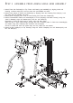
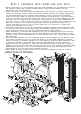
ST E P 2 A SSE M B L E PR E SS A R M & C A B L E A R M A SSE M B L Y
6
1. Attach Press Arm Selector(8) to Top Frame with bearing pre-installed(5) by aligning holes and
inserting 19.95mm Axle(31A). Lock into place with pre-installed set screw.
2. Attach Press Arm(9) to Press Arm Selector(8) by aligning holes and inserting Pivot Axle(31). Lock
into place with pre-installed set screw.
3. Attach 50mm Plugs(41) onto ends of Press Arm(9) and Press Arm Selector(8).
4. Attach Pre-assembled Cable Arm Assembly(20) to Front Upright(4) and Base Frame(1) using four
3/8"X 3" Bolts(88), eight 3/8" Washers(101) and four 3/8" Nuts(107).
Remember to keep all bolts loose to ensure holes will align easily.
Slide the axle of each Cable Arm(21) through the hole in selector plate of Cable Arm Assembly(20)
and fasten using Axle Collar(36) with 5/16"X1/4" Set Screw(99).
Check to ensure that each arm pivots freely and any cables are not twisted.
5. Attach Lat Bar Holder(18) to Top Frame(5) using two 3/8"X3" Bolts(88), four 3/8" Washers(101) and
two 3/8" Nuts(107).