OWNER’S MANUAL Trimmer/Mower SAFETY FIRST! Before operating this equipment, read this Owner's Manual and the separate manual supplied by the engine manufacturer.
Table of Contents Dear Owner: You now own one of the finest trimmer/mowers available. It was designed to easily handle a wide variety of trimming, mowing and clearing chores. You will find the machine to be an invaluable tool in caring for your property. Please carefully read this Manual. It tells you how to safely and easily assemble, operate and maintain your machine. Be sure that you and any other operators carefully follow the recommended safety practices at all times.
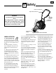
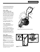
1 Section 1 Safety Trimmer Head Control Bail Engine Throttle Control Lever IMPORTANT Safe Operation Practices for Walk-Behind Mower Keyswitch (Electric Start Model) This cutting machine is capable of amputating hands and feet and throwing objects. Failure to observe the following safety instructions could result in serious injury or death. Handlebar Height Adjuster Cutting Height Settings Figure 1-1 - Electric start model shown. GENERAL OPERATION 1.
2 Section 1: Safety 20. Always wear approved safety goggles or safety glasses with side shields when operating equipment. The use of any powered machine can result in foreign objects being thrown by high-speed rotating parts which can cause personal injury or property damage. Stay away from glass and other easily thrown or breakable objects. 21. Wear work gloves and sturdy footwear when using this equipment. Leather work shoes or short boots are ideal.
Section 1: Safety 5. Never tamper with safety devices. Check their proper operation regularly. 6. To reduce fire hazard, keep mower free of grass, leaves or other debris build-up. Clean up oil or fuel spills. Let machine cool before storing. 7. After striking an object, stop the engine and disconnect the spark plug wire. Inspect the machine and repair, if necessary, before restarting. 8. Never make adjustments or repairs while engine is running. 9.
4 Section 2 Assembly WARNING To prevent personal injury or property damage, do not attempt to start the engine until all assembly steps are complete and you have read and understand all of the safety and the operating instructions in this Manual. INTRODUCTION Carefully follow these assembly steps to correctly prepare your machine for use. It is recommended that you read this Section in its entirety before beginning assembly.
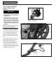
Section 2: Assembly 5. Use two cable ties (F, Figure 2-2) to secure the trimmer head control cable (C) and the electrical wiring harness (O) to the handlebar at the locations shown. 5 A G STEP 3: ATTACH THROTTLE CONTROL LEVER C 1. One end of the Throttle Control Cable (H, Figure 2-3) is attached to the engine. Gently unwind the cable from its shipping position and position the Throttle Control Lever (I) on the outside of the right handlebar, next to the throttle control decal. 2.
6 Section 2: Assembly STEP 6: CONNECT AND CHARGE BATTERY (ELECTRIC START MODELS) X DANGER • Wet conditions can cause an electric shock hazard during battery recharging. Avoid wet conditions when charging battery. P • Recharging the battery with improper equipment could cause a battery explosion. Use only the battery charger shipped with the unit. The engine must be shut off and the spark plug wire disconnected and moved away from the spark plug.
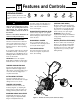
7 Section 3 Features and Controls OPERATING SYMBOLS STOP Various symbols (shown here, with word descriptions) are used on the unit. ENGINE STOP WARNING Before operating your machine, carefully read and understand all safety, controls and operating instructions in this Manual, the separate Engine Owner’s Manual, and on the decals on the machine. Failure to follow these instructions can result in serious personal injury.
8 Section 4 Operation WARNING Before operating your machine, carefully read and understand all safety (Section 1), controls (Section 3) and operating instructions (Section 4) in this Manual, in the separate Engine Owner’s Manual, and on the decals on the machine. Failure to follow these instructions can result in serious personal injury. INTRODUCTION Read this Section thoroughly before you start the engine.
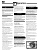
Section 4: Operation 9 USE THE CORRECT DIAMETER TRIMMER LINE STARTING THE ENGINE Before starting a project, examine the grass or material you will be cutting and trimming. 2. Connect the spark plug wire to the spark plug. For tougher conditions, use two (or four) sections of the thicker gauge, .155" diameter extra-heavy duty line. For less demanding conditions, use two sections of the thinner gauge, .130" diameter heavy-duty line.
10 Section 4: Operation CLEAN THE TRIMMER/MOWER ON A REGULAR BASIS VARY THE THROTTLE SETTING ACCORDING TO CONDITIONS THROWN OBJECT HAZARD • Objects such as rocks, pebbles, and small debris will be thrown violently by the cutting head, resulting in significant hazard to eyes and exposed body parts. • Always wear safety-approved eye protection and suitable clothing and footwear. • Keep children, pets and bystanders 50 feet away from machine while operating. • Be alert to hidden obstacles.
11 Section 5 Maintenance WARNING Before inspecting, cleaning or servicing the machine, shut off engine, disconnect spark plug wire, and make sure that all moving parts have come to a complete stop. Remove ignition key on electric start models. Failure to follow these instructions can result in personal injury or property damage. NOTE: LEFT and RIGHT sides of unit are as viewed from operator’s position behind the handlebars.
12 Section 5: Maintenance WARNING Before inspecting, cleaning or servicing the machine, shut off engine, wait for all moving parts to come to a complete stop, disconnect spark plug wire and move wire away from spark plug. Failure to follow these instructions can result in serious personal injury or property damage. REMOVING AND REPLACING THE TRIMMER HEAD INSPECTING / REPLACING THE DRIVE BELT 1. Stop the engine and wait for all moving parts to stop.
13 Section 5: Maintenance WARNING Before inspecting, cleaning or servicing the machine, shut off engine, wait for all moving parts to come to a complete stop, disconnect spark plug wire and move wire away from spark plug. Failure to follow these instructions can result in serious personal injury or property damage. 11.
14 Section 5: Maintenance WARNING Before inspecting, cleaning or servicing the machine, shut off engine, wait for all moving parts to come to a complete stop, disconnect spark plug wire and move wire away from spark plug. Failure to follow these instructions can result in serious personal injury or property damage. TRIMMER/MOWER CLEANING AND DEBRIS REMOVAL Thorough and regular cleaning of debris from the engine and the machine is required for maximum engine efficiency and good overall performance.
15 Section 5: Maintenance WARNING Before inspecting, cleaning or servicing the machine, shut off engine, wait for all moving parts to come to a complete stop, disconnect spark plug wire and move wire away from spark plug. Failure to follow these instructions can result in serious personal injury or property damage.
16 Section 5: Maintenance WARNING Before inspecting, cleaning or servicing the machine, shut off engine, wait for all moving parts to come to a complete stop, disconnect spark plug wire and move wire away from spark plug. Failure to follow these instructions can result in serious personal injury or property damage. CHANGING TRIMMER LINES The trimmer lines will wear with use and eventually require replacement.
Section 5: Maintenance 17 WARNING Before inspecting, cleaning or servicing the machine, shut off engine, wait for all moving parts to come to a complete stop, disconnect spark plug wire and move wire away from spark plug. Failure to follow these instructions can result in serious personal injury or property damage.
18 Parts List Models 52068 & 52069 DRAWING NO.
Parts List 19 Models 52068 & 52069 PARTS LIST – DRAWING NO. 1 Ref. # 1 2 3 4 5 6 7 8 9 10 11 12 13 14 Part # 1917765 1918741 1918415 1917407001 1754128 9534 * 1903584 1917728 1100243 1100009 1918814 1903588 1917144001 Description Debris Guard ............................................ Decal-Logo .............................................. Push-in Fastener....................................... Debris Guard Support............................... Hex Flange Screw, 1/4-20 x 3/4 ................
20 Parts List Models 52068 & 52069 DRAWING NO. 2 See DRAWING NO. 3 1 2 3 7 8 9 10 6 1 4 See DRAWING NO. 1 3 19 18 11 2 20 12 23 21 18 Ref. # 25 14 26 15 27 16 17 18 PARTS LIST – DRAWING NO.
Parts List 21 Models 52068 & 52069 PARTS LIST – DRAWING NO. 3 DRAWING NO. 3 Ref. # 4 1 2 3 4 5 6 7 8 9 10 11 12 13 14 15 16 11 6 10 2 12 3 Part # Description Qty. 1 6 5 7 9 8 13 1918283 1915889 1918304 1918070001 1917589 1908677 1749977001 1983658 1185814 1918081 1100807 1110106 1763682 1100799 1917145001 1732499 Upper Handlebar (Incl. Refs. 2 & 3) ....... Decal–Bail Engage/Disengage ................ Decal–Throttle ....................................... Control Bail–Trimmer Head ......
CUSTOMER SERVICE INFORMATION Owner Registration Card Please fill out and mail the enclosed owner registration card. The purpose of this card is to register each unit at the factory so that we can provide you with warranty benefits and informational bulletins. Customer Service and Technical Service If you have questions or problems with the unit, contact your local dealer or the factory. (When calling or writing, provide the Model/Serial Numbers of the unit.