BOLTEK CORPORATION Lightning Detection EFM-100 Atmospheric Electric Field Monitor Installation/Operators Guide EFM100-1000120-060414
BOLTEK LIGHTNING DETECTION EFM-100 Atmospheric Electric Field Monitor Disclaimer EFM-100 lightning data is only approximate and should not be used for safety applications. Strike and storm locations indicated and alarm statuses may be erroneous and should not be used to safeguard personnel, equipment or data.
FCC Compliance Statement For United States Users This equipment is tested and found to comply with the limits for a Class B digital device, pursuant to Part 15 of the FCC Rules. These limits are designed to provide reasonable protection against harmful interference in a residential installation. This equipment generates, uses, and can radiate radio frequency energy and, if not installed and used in accordance with the instructions, may cause harmful interference to radio or television reception.
CAUTIONS EFM-100 lightning data is only approximate and should not be used for safety applications. Strike and storm locations indicated and alarm statuses may be erroneous and should not be used to safeguard personnel, equipment or data. Install the EFM-100 Field Mill on a calm clear day when no thunderstorms are expected. If you are not experienced in safe antenna installation using appropriate safety equipment you should refer installation to an experienced antenna installer.
Table of Contents INTRODUCTION .......................................................................................................1 THEORY OF OPERATION .........................................................................................2 INSTALLATION .........................................................................................................5 EFM-100 DISPLAY SOFTWARE INSTALLATION .....................................................6 EFA-20 USB DRIVER INSTALLATION ....................
Table of Figures Figure 1: Electric Field Mill at Ground Level ................................................... 3 Figure 2: Intensification of Electric Field ......................................................... 3 Figure 3: Field Mill Block Diagram .................................................................. 4 Figure 4: EFM-100 Connection Diagram ......................................................... 5 Figure 5: A poor choice of mounting locations ............................................
C H A P T E R 1 - I N T R O D U C T I O N 1 Chapter Introduction Congratulations on your purchase of a Boltek EFM-100 Electric Atmospheric Electric Field Monitor. The EFM-100 is a low cost, high quality atmospheric electric field monitor which uses your personal computer to display and record data. The EFM-100 not only detects nearby lightning but can also detect the high electric field conditions which preceded lightning.
C H A P T E R 1 - I N T R O D U C T I O N 1 AC wall adapter power supply 120VAC to 12VDC for North America 220VAC to 12VDC for Europe 1 field mill grounding wire 6 sensitivity plugs (0.75X, 0.63X, 0.5X, 0.33X, 0.25X, 0.2X) 1 mast (¾” NPT X 6”) 1 mounting flange 1 CDROM containing Windows software and USB drivers 1 user manual (this is it) Unpack your EFM-100 and make sure all the parts are included. Theory of Operation Electric fields develop wherever there is a difference in electric potential.
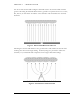
C H A P T E R 1 - I N T R O D U C T I O N For an accurate electric field reading the field mill needs to be mounted flush with the ground. Mounting the field mill flush with the ground is not practical however as water, dirt, insects, etc will collect around the sense electrodes and contaminate the electrode insulators. Figure 1: Electric Field Mill at Ground Level Mounting the electric field mill above the ground surface will enhance the electric field resulting than an incorrect high reading.
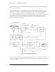
C H A P T E R 1 - I N T R O D U C T I O N The EFM-100’s electric field mill senses electric field by repeated exposing and shielding a series of sense electrodes. An electric field mill uses a mechanical chopper to alternately shield and expose several sense plates to an electric field. When the sense plates are exposed to the electric field an electric charge is drawn from ground to the plates through a sense resistor.
C H A P T E R 2 - I N S T A L L A T I O N 2 Chapter Installation Connect and test your EFM-100 on the ground before permanently mounting the sensor unit. Install the software on your computer and connect the field mill as shown below. The field mill should respond to charged objects brought near it. Most plastic objects can be easily charged by rubbing them on your clothes.
C H A P T E R 2 - I N S T A L L A T I O N EFM-100 Display Software Installation Insert the provided EFM-100 Software CD into your CD-ROM drive. The setup program should start automatically. If the setup program does not start automatically you can start it manually by clicking on Start…Run…, type d:setup.exe then click OK. Once the software is installed you can run the EFM-100 display software by clicking on Start…All Programs...Boltek…EFM-100 Electric Field Monitor.
C H A P T E R 2 - I N S T A L L A T I O N Hardware Installation The EFM-100 field mill mounts on a ¾” NPT (National Pipe Thread) threaded pipe (Note that ¾” NPT pipe measures 1” outside diameter) A short length of ¾” NPT threaded pipe and a ¾” NPT mounting flange are provided for mounting the field mill on a horizontal surface. Longer lengths of threaded pipe are available at your local hardware store.
C H A P T E R 2 - I N S T A L L A T I O N Mounting the field mill close to tall objects will result low readings as the tall object will shield the field mill sensor. + + + + + + + + + + + + + + + - - - - - - - - - - - - - - Figure 5: A poor choice of mounting locations Avoid mounting the field mill in a location where it will be shielded by buildings, tree, or other tall objects. Mount your field mill with similar considerations given to an anemometer.
C H A P T E R 2 - I N S T A L L A T I O N EPM-1 Power Module The EPM-1 power module is a connection point for sending DC power up to the field mill and connecting to analog signals from the field mill. Figure 7: EPM-1 Power Module Connectors Field Mill Power Cable Connector Connect the black cable from the EPM-1 Power Module’s field mill power connector to the field mill power connector. The cable supplies 12VDC to the field mill and carries the analog output signals back to the EPM-1.
C H A P T E R 2 - I N S T A L L A T I O N Analog Output Analog output is available on the EPM-1 Power Module. Output voltage is 1V per kV/m differential, ranging from +20V corresponding to +20kV/m to -20V corresponding to -20kV/m. Note that EPM-1 connections are directly connected to the field mill and a lightning hazard exists at those connections. LIGHTNING HAZARD EPM-1 connections are not optically isolated from the roof mounted field mill.
C H A P T E R 2 - I N S T A L L A T I O N EFA-10 Fiber Optic Adapter The EFA-10 Fiber Optic Adapter converts the optical data from the field mill to an electrical signal compatible with your personal computer. Data is transmitted optically from the field mill at 9600 baud, 8 data bits, 1 stop bit, no parity. Figure 10: EFA-10 Fiber Optic Adapter The EFA-10 converts this optical data stream to an electrical signal compatible with your computer’s RS232 COM port.
C H A P T E R 2 - I N S T A L L A T I O N ST Fiber Optic Connectors The EFM-100 transmits its data over a fiber optic cable. The fiber optic cable uses St style connectors on each end. Figure 12: Female Fiber Optic Connector If the field mill installer is not familiar with ST fiber optic connectors he should familiarize himself with the connectors on the ground, before mounting the field mill on the roof.
C H A P T E R 2 - I N S T A L L A T I O N Figure 14: EFM-100 Field Mill Connections Power Connector Connect the black cable from the field mill’s power connector to the EPM-1 Power Module’s field mill power connector. The cable supplies 12VDC to the field mill and carries the analog output signals back to the EPM-1. See the Lightning Hazard caution in the EPM-1 Analog Output section of this manual.
C H A P T E R 2 - I N S T A L L A T I O N Sensitivity Connector The sensitivity connector accepts a sensitivity plug to reduce the sensitivity of the field mill. Several different values are provided so you can choose an appropriate value for your installation. See Chapter 1: Intensification of Electric Field for a description of why this is necessary. Figure 15: Sensitivity Plugs With no plug installed the field mill has a relative sensitivity of 1.
C H A P T E R 2 - I N S T A L L A T I O N Figure 16: Correcting a Field Mill using a Reference Field Mill correction reference permanent Once you have calculated the required sensitivity reduction (correction factor) you can calculate the resistor value needed for the Sensitivity Plug. resistor 100k 100k (1 correction) For most installations it is not necessary to correct using a reference field mill.
C H A P T E R 2 - I N S T A L L A T I O N Grounding Detail The EFM-100 field mill needs to be grounded for proper operation and for lightning and electrical safety. Connect the connector end of the green ground wire to the field mill ground connector. Connect the other end of the green ground wire and the field mill mounting hardware to your building’s central ground through a #6 bare ground wire or other suitable wire according to your local electrical code.
C H A P T E R 2 - I N S T A L L A T I O N Figure 17: Field Mill Grounding Detail 17
C H A P T E R 3 – C O N F I G U R I N G T H E S O F T W A R E 3 Chapter Configuring the Software EFM Options: General Figure 18: EFM Options – General Number of Data Sources Enter the number of field mills for which you would like to display data. The minimum number is 1 field mill. The maximum number is four field mills. If you have more than four field mills you will require a second computer for each additional four field mills creating a multi-monitor display.
C H A P T E R 3 – C O N F I G U R I N G T H E S O F T W A R E Data Source Name Enter a descriptive name for each field mill. If you are displaying the data from more than one field mill the name will be used to identify the source of the data. Select individual field mills in the Field Mill Selection box above. Enabled Checkbox Check this checkbox to enable the display of data for the currently selected field mill.
C H A P T E R 3 – C O N F I G U R I N G T H E S O F T W A R E EFM Options: High Field Alarm Figure 19: EFM Options – High Field Alarm Field Mill Selector Select the field mill for which you would like to enable or disable High Field Alarm. Setpoint High Field Alarm Setpoint is the magnitude of electric field required to trigger a High Field Alarm. For example, with a setpoint of 1 kV/m the alarm will activate if the field goes above 1 kV/m or below -1 kV/m.
C H A P T E R 3 – C O N F I G U R I N G T H E S O F T W A R E High Field Alarm Duration High Field Alarm Duration is the length of time the High Field Alarm will remain active once the field drops below the alarm setpoint. WAV File Checkbox Check the checkbox to enable the playing of WAV file sound when the High Field Alarm activates. Clear the checkbox to disable the playing of the WAV sound.
C H A P T E R 3 – C O N F I G U R I N G T H E S O F T W A R E Field Mill Selector Select the field mill for which you would like to enable or disable Very High Field Alarm. Setpoint Very High Field Alarm Setpoint is the magnitude of electric field required to trigger a Very High Field Alarm. For example, with a setpoint of 1 kV/m the alarm will activate if the field goes above 1 kV/m or below -1 kV/m.
C H A P T E R 3 – C O N F I G U R I N G T H E S O F T W A R E EFM Options: Lightning Alarm Figure 21: EFM Options – Lightning Alarm Field Mill Selector Select the field mill for which you would like to enable or disable alarms. Enable Lightning Alarm Checkbox Check this option to enable the lightning alerts for the currently selected field mill. Active Duration Lightning Alarm Duration is the length of time the lightning alarm will remain active after a lightning event is detected.
C H A P T E R 3 – C O N F I G U R I N G T H E S O F T W A R E Only Announce Approaching Strokes Check this option to play lightning strike distance WAV sounds only as strikes get closer. This option will reduce the frequency of the WAV sounds for heavy storms that are detected at the same distance or further away. WAV Filenames The WAV Filename is the file which will play out the computer speakers when the On Activation, Distance, Repeat, or All Clear is activated.
C H A P T E R 3 – C O N F I G U R I N G T H E S O F T W A R E EFM Options: Delta Alarm Figure 22: EFM Options - Delta Alarm Field Mill Selector Select the field mill for which you would like to enable or disable alarms. Setpoint Delta Alarm Setpoint is the change of the electric field magnitude required to trigger a Delta Alarm. For example, with a setpoint of 1 kV/m the Delta Alarm will activate if the field increases or decreases by 1 kV/m or more within the set interval time.
C H A P T E R 3 – C O N F I G U R I N G T H E S O F T W A R E the electric field difference must remain above 1 kV/m or below -1 kV/m for 30 seconds before the alarm activates. Duration Delta Alarm Duration is the length of time the Delta Alarm will remain active once the Delta Alarm is triggered. WAV File Checkbox Check the checkbox to enable the playing of WAV file sound when the Delta Alarm activates. Clear the checkbox to disable the playing of the WAV sound.
C H A P T E R 3 – C O N F I G U R I N G T H E S O F T W A R E EFM Options: Data Logging Figure 23: EFM Options – Data Logging Field Mill Selector Select the field mill for which you would like to configure data logging. Enable Data Logging Checkbox Check the Enable Data Logging checkbox if you would like field mill data to be logged to the hard drive for the field mill selected in the selection box above. Logged data is viewable using the EFMView Electric Field Mill Data Viewer.
C H A P T E R 3 – C O N F I G U R I N G T H E S O F T W A R E EFM Options: Data Sharing Figure 24: EFM Options – Data Sharing Field Mill Selector Select the field mill for which you would like to configure data sharing. Enable Sharing Checkbox Check the Enable Sharing checkbox if you wish to share your field mill data with others. If enabled your EFM-100 software will list on the Listen Port for incoming connections.
C H A P T E R 3 – C O N F I G U R I N G T H E S O F T W A R E EFM Options: Alerts Figure 25: EFM Options – Email & SMS Alerts Field Mill Selector Select the field mill for which you would like to configure data sharing. Alarm Checkbox Select the messages you wish to receive. Active will send messages when an alarm or fault is first triggered, Clear will send messages after the selected alarm(s) are cleared based on the settings input for the High, Very High, and Lightning alarm settings.
C H A P T E R 3 – C O N F I G U R I N G T H E S O F T W A R E SMS Recipients Click the Add button to enter a new cell phone number for receiving the activated alert messages. To change or remove an existing contact, first select the phone number to highlight, then click Edit to change, or Delete to remove it from the list. Email Configuration Select the E-Mail checkbox to enable email alerts. Click on the settings icon to configure the outgoing email server.
C H A P T E R 3 – C O N F I G U R I N G T H E S O F T W A R E SMS by Modem Configuration Select the SMS by Modem checkbox to enable alerts to be sent through a SMS Modem. Click on the settings icon to select the Com Port, baud rate and any special commands that may be required to operate the modem. Figure 27: SMS Modem Configuration Please refer to your SMS Modem documentation for setup and access.
C H A P T E R 4 - 4 Chapter O P E R A T I O N Operation The EFM-100 display software interprets and displays the field mill readings and status. For remote field mills the software also attempts to establish and maintain a network connection with the remote computer’s EFM-100 display software in order to receive the remote data. When Data Sharing is enabled the display software will accept remote connections and deliver its field mill data over those connections for others to view.
C H A P T E R 4 - O P E R A T I O N Location Descriptor describes the location of the field mill. When the software is configured to display data from multiple field mills the descriptor is important in identifying the source of the data. The History Graph shows the most recent data in graphical form. The history graph is useful in identifying trends in electric field. Zoom Handles are used for zooming in on an area of interest in the trend graph.
C H A P T E R 4 - O P E R A T I O N Interpreting the Data Display Often the first indication of an approaching thundercloud is a positive field reading followed by a field reversal to a negative field as the cloud moves overhead Figure 30: Approaching Thundercloud Figure 31: Increasing Field due to Approaching Thundercloud 35
C H A P T E R 4 - O P E R A T I O N Figure 32: Thundercloud Directly Overhead Figure 33: Electric Field Polarity Reversal With the thundercloud directly overhead the polarity of the field has reversed to a negative electric field.
C H A P T E R 4 - O P E R A T I O N Figure 34: Departing Thundercloud Figure 35: End of Storm Oscillation Once the cloud has passed over the field will often reverse back to positive before decaying to a normal fair-weather electric field reading of about 0.1 kV/m. This field reversal at the end of the storm has been referred to as the “End of Storm Oscillation” (ESO).
C H A P T E R 4 - O P E R A T I O N Figure 36: Step Changes in Field Magnitude Indicate Lightning Step changes in the magnitude of the electric field indicate lightning. Closer lightning produces larger field changes than distant lightning. The EFM-100 can detect lightning out to about 24 miles. Figure 37: Precipitation Noise Rain, snow, and dust can carry an electric charge.
C H A P T E R 5 - 5 Chapter MA I N T E N A N C E Maintenance Your EFM-100 should run for years with very little maintenance. An occasional cleaning may be all that is necessary. In most installations even that will not be necessary as rain will wash away any accumulated dirt. Periodically inspect your field mill to ensure the Teflon insulators are free from dirt or contamination. Watch for spider webs or other debris which could short an electrode to ground (the case.
A P P E N D I X A – T R O U B L E S H O O T I N G A Appendix Troubleshooting Problem: Signal Lost Fault Solution: The EFM-100 software will report a “signal lost” fault if it does not receive data from the field mill for more than a few seconds. You will need to determine why the data is not reaching the software. Possible causes will depend on the type of field mill connection: USB/RS-232 or network.
A P P E N D I X A – T R O U B L E S H O O T I N G Problem: Rotor Fault Solution: The EFM-100 field mill continuously monitors the speed of the rotor and ensures it is spinning at the correct speed. If the rotor is found to be spinning either too fast or too slow the supervisory circuitry will change the fault status in the data stream from a 0 (no fault) to a 1 (rotor fault.) The EFM-100 display software will indicate a Rotor Fault. The field mill rotor may have become obstructed.
A P P E N D I X B – E F M - 1 0 0 D A T A F O R MA T B Appendix EFM-100 Data Format The EFM-100 Electric Field Mill transmits data sentences down the fiber optic cable at the rate of twenty readings per second. The EFA-10 converts the optical signal to standard RS232 at 9600 baud, 8 data bits, no parity, 1 stop bit. Electric Field Sentence $
,* - polarity of electric field + or - electric field level 00.00 to 20.
A P P E N D I X C – S P E C I F I C A T I O N S C Appendix Specifications EFM-100 Hardware Specifications Electric Field Range: -20 kV/m to +20 kV/m Typical Range of Interest: -5 kV/m to +5 kV/m Response Time: 0.1 seconds Resolution: Digital Data Cable: Digital Data Format: RS232: Digital Output Analog Output 0.01 kV/m Infinite 50/125 Multi Mode Fiber Optic Cable with ST Connectors $
A P P E N D I X C – S P E C I F I C A T I O N S EFM-100 Weight: 2.2 lbs (1 kg) Shipping Weight: 13 lbs (5.